Aerodynamic Air Bearings

An air bearing and gas power technology, which is applied in the field of turbine shafts, can solve the problems of screw box hole wear, screw and bearing box loose connection, etc.

Active Publication Date: 2019-03-12
BOSCH MAHLE TURBO SYST GMBH & CO KG
View PDF6 Cites 0 Cited by
  • Summary
  • Abstract
  • Description
  • Claims
  • Application Information

AI Technical Summary

Problems solved by technology

Another disadvantage is the loose connection of the screws to the bearing housing
During the radial movement of the bushing, the screw moves in the radial bore of the box, which leads to wear of the screw and / or the box bore
This wear then leads to greater movement between the screw and the bearing housing, so that ideal positioning of the bushing through the screw is no longer achieved

Method used


Image

  • Aerodynamic Air Bearings
  • Aerodynamic Air Bearings
  • Aerodynamic Air Bearings

Examples


Embodiment Construction

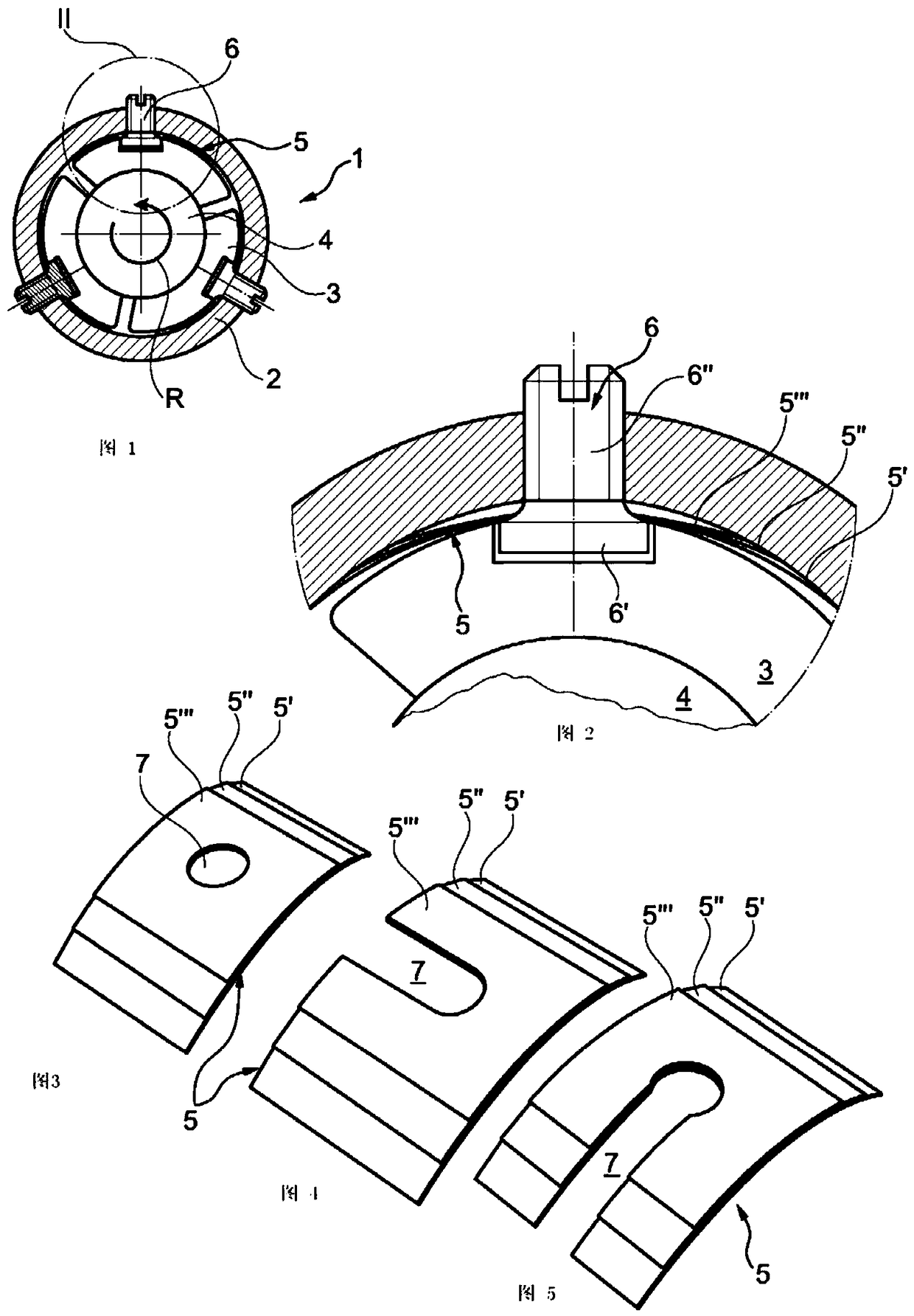
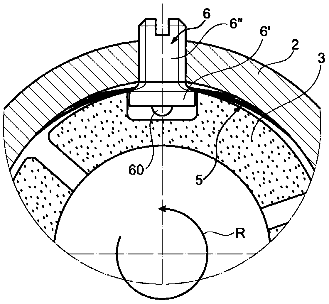
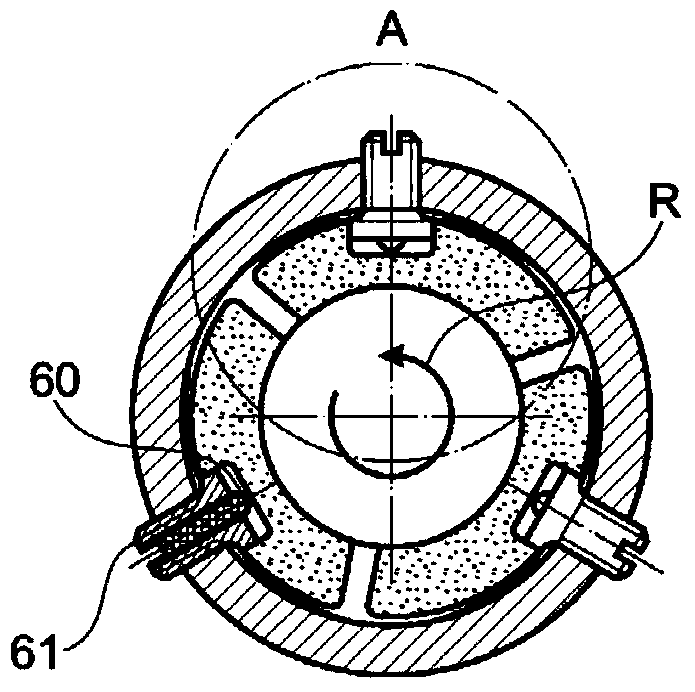
[0022] according to figure 1 , the air bearing 1 comprises a bearing housing 2 having in particular a circular recess in which at least three bushings 3 are arranged which together surround and fit a shaft 4 . Between the inner circumference of the recess of the bearing housing 2 and the opposite outer side of each bushing 3, a retaining spring arrangement in the form of a leaf spring 5 is arranged, which is tensioned with its longitudinal ends against the bearing housing 2 The inner circumference of the central recess, and in the direction of the opposite outer side of the corresponding bearing 3, is tensioned against with its central region. The sleeve 3 is kept fixed in the bearing axis direction, which is perpendicular to the plane of the drawing, or the axis direction of the central axis of the recess of the bearing housing 2, and the circumferential direction of the shaft 4 passing through the screw 6, which is respectively The head 6' protrudes into a recess on the out...


PUM


Abstract

The invention relates to an air bearing having a bushing arranged in an annular box and co-mounting a rotatable shaft. Each bushing is movably mounted on a radial screw, which screw is adjustably arranged in the box and projects into a corresponding recess in said bushing. Each screw passes through a leaf spring, which is inserted between the box and the bushing to eliminate movement of the bushing and press the bushing against the shaft. The spring travel of the leaf spring is adjustably limited by a stop body or the head of an adjustable screw.

Description

technical field [0001] This invention relates to aerodynamic air bearings for radially mounted shafts, in particular turbine shafts. Background technique [0002] Such air bearings are the subject of CZ 2003 3062 A. In this known air bearing, screws radial to the bearing shaft are screwed adjustably on the outside into each bushing, said screws being arranged axially displaceable in the bearing cage with a smooth shank region. in radial holes. This possible axial displacement path is defined on the one hand by a collar arranged on a screw provided on the opposite interior of the bushing and bearing cage, and on the other hand by an adjustable nut which adjustably Screws into a threaded portion on the distal end of the hub of the pin and interacts with a stop surface on the outer box. A retaining spring arrangement designed as a leaf spring is arranged or clamped between the collar and the inner side of the bearing housing. [0003] The disadvantage of this solution is th...

Claims


Application Information

Patent Timeline
Patent Type & Authority Patents(China)
IPC IPC(8): F16C27/02
CPCF16C17/03F16C25/02F16C27/02F16C33/1005F16C2360/24F16C2226/60F04D29/057
Inventor 马哈尔·克卢萨切克
Owner BOSCH MAHLE TURBO SYST GMBH & CO KG
Why Eureka
Try Eureka