Street lamp pole with air purification function
A technology for air purification and street light poles, which is applied in the parts of lighting devices, outdoor lighting, lighting and heating equipment, etc., can solve the problem that street light poles cannot purify the air, etc., and achieve the effect of health protection
- Summary
- Abstract
- Description
- Claims
- Application Information
AI Technical Summary
Problems solved by technology
Method used
Image
Examples
Embodiment 1
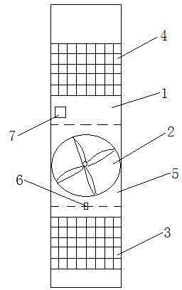
[0013] Such as figure 1 As shown, this embodiment provides a street light pole with air purification function, including a hollow light pole 1 and a circuit board arranged in the light pole 1, and an exhaust fan 2 is arranged in the light pole 1, and the exhaust fan 2 passes through a solenoid valve It is connected in parallel with the power supply of the circuit board in the light pole 1. The light pole is provided with an air inlet 3 and an air outlet 4. The air inlet 3 is arranged below the hood 2, and the air outlet 4 is arranged above the hood 2. A dust filter cover is arranged on the inner wall of the air outlet 4; an anion generator 7 is fixed inside the light pole 1.
[0014] The lamp pole is managed uniformly by the street lamp control and management center, the electromagnetic valve is started by remote control, the exhaust fan 2 is turned on, and the dirty air is sucked into the lamp pole 1 through the air inlet 3 by the exhaust fan 2, and the air is filtered throug...
Embodiment 2
[0016] On the basis of Embodiment 1, a door 5 is provided at the position corresponding to the exhaust fan 2 on the light pole 1 provided in this embodiment, one side of the door 5 is connected to the light pole 1 through a hinge, and a lock hole 6 is provided on the other end of the door 5 , the light pole 1 is provided with a lock hole 6 corresponding to the door 5 .
[0017] The door 5 and the keyhole 6 are provided to facilitate the maintenance and maintenance of the exhaust fan 2, and at the same time, it is beneficial to the anti-theft management.
Embodiment 3
[0019] It is basically the same as the above embodiment, the difference is that the air inlet 3 and the air outlet 4 are both arranged on the side of the light pole 1 facing the road, and baffles are arranged outside the air inlet 3 and the air outlet 4; the air inlet 3, the outlet The tuyere 4 and the door 5 are both arranged within 1.5 meters from the light pole 1 to the ground.
[0020] According to the emission height of automobile exhaust, the concentration of exhaust gas is relatively high in the space 1.5 meters above the ground. The position of air inlet 3, air outlet 4 and door 5 is set to facilitate the purification of automobile exhaust, and at the same time, it is beneficial for sanitation workers to use exhaust fans 2. As for the maintenance of the dust filter, the setting of the baffle is beneficial to block the blockage or damage of the light pole by wind and rain, leaves, paper, etc. when the air is not purified.
PUM
 Abstract
Description
Claims
Application Information
 - R&D
- Intellectual Property
- Life Sciences
- Materials
- Tech Scout
- Unparalleled Data Quality
- Higher Quality Content
- 60% Fewer Hallucinations
Browse by: Latest US Patents, China's latest patents, Technical Efficacy Thesaurus, Application Domain, Technology Topic, Popular Technical Reports.
© 2025 PatSnap. All rights reserved.Legal|Privacy policy|Modern Slavery Act Transparency Statement|Sitemap|About US| Contact US: help@patsnap.com

