
A saturable reactor with resistance forming bias voltage

A reactor and resistance technology, applied in the field of saturable reactors, can solve the problems of complex manufacturing process, inability to realize the optimal design of saturable reactors, and large influence of saturable reactor characteristics, achieving simple manufacturing process, easy optimization design, reduction of Effects of Transient Time

Inactive Publication Date: 2016-08-31
SHANDONG UNIV
View PDF4 Cites 0 Cited by
  • Summary
  • Abstract
  • Description
  • Claims
  • Application Information

AI Technical Summary

Problems solved by technology

However, the existing saturable reactor coil needs taps, and the manufacturing process is complicated
The tap position has a great influence on the characteristics of the saturable reactor. After the tap position is determined, it cannot be changed, and the optimal design of the saturable reactor cannot be realized.

Method used


Image

  • A saturable reactor with resistance forming bias voltage

Examples


Embodiment 1

[0026] The present invention will be further described below in conjunction with the accompanying drawings and embodiments.

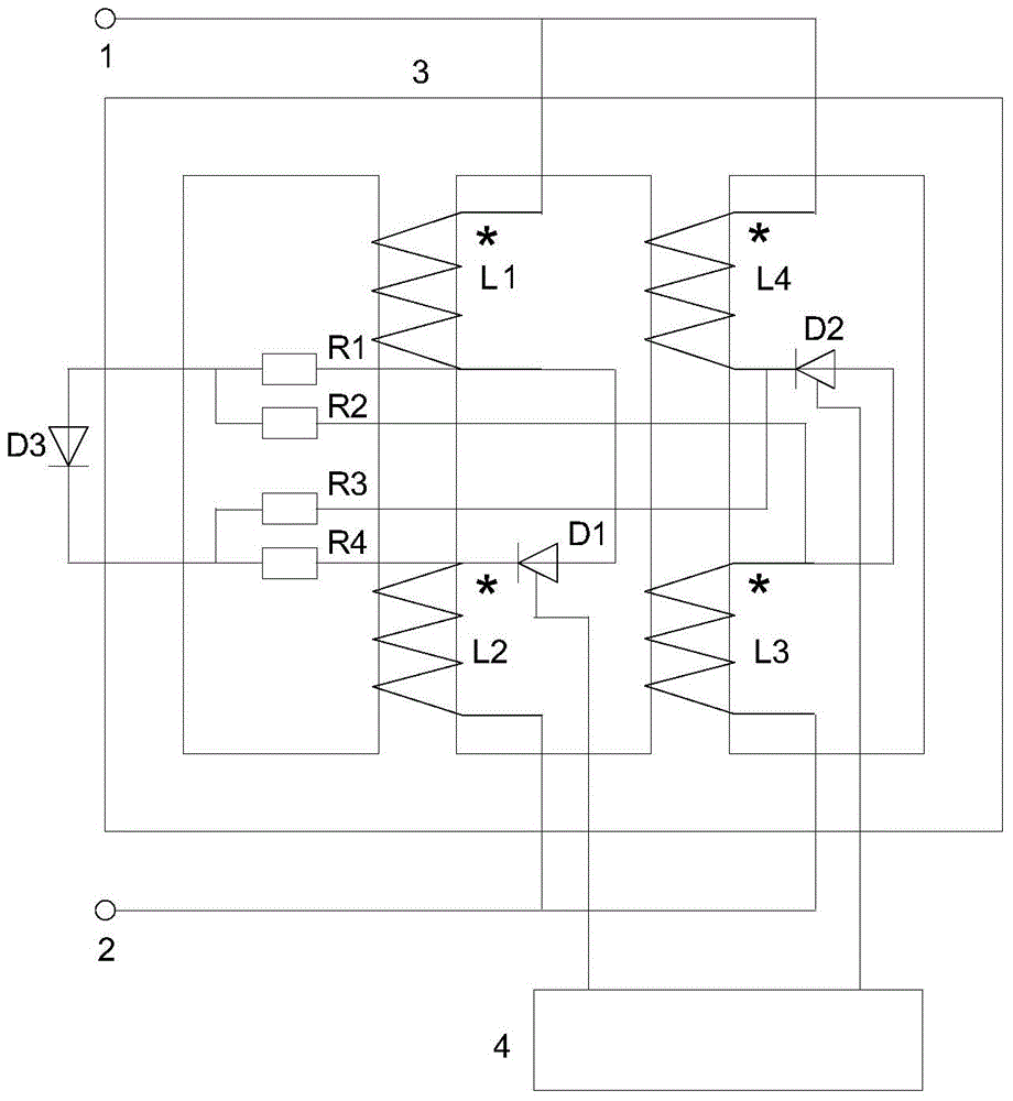
[0027] The structure and connection method of a saturable reactor in which the resistance forms a bias voltage is as follows: figure 1 shown. Including saturable reactor terminal I1, saturated reactor terminal II2, saturated reactor closed-loop iron core 3, and control circuit 4. The closed-loop iron core 3 of the saturable reactor has at least two iron core columns with the same cross-sectional area and at least two coils; each of the two iron core columns has at least one magnetic flux closed loop that does not pass through the opposite iron core column. One of the iron core columns has a coil L1 and a coil L2, and the other iron core column has a coil L3 and a coil L4; the number of turns of the coil L1, the coil L2, the coil L3, and the coil L4 is equal.

[0028] The closed-loop iron core 3 may be two closed-loop iron cores that have no passages t...


PUM

PropertyMeasurementUnit
electrical resistanceaaaaaaaaaa

Abstract

The invention relates to a saturation resistor for forming bias voltage through resistance. The reactor comprises a closed loop iron core, wherein two iron core columns of the closed loop iron core are provided with at least two coils respectively; the number of turns of each coil is the same; the two iron core columns are provided with a homonymous end connecting terminal I of one coil respectively and a heteronymous end connecting terminal II of the other coil respectively; a thyristor is forwardly connected in series between remaining terminals of the two coils of one iron core column; another thyristor is reversely connected in series between remaining terminals of the two coils of the other iron core column; a control terminal of each thyristor is connected with a control circuit; a pair of resistors are connected in series between positive electrodes of the two thyristors; another pair of resistors are connected in series between negative electrodes of the two thyristors; the resistance values of the four resistors are equal; a node between the two pairs of resistors is connected with a diode; the size of a trigger angle of each thyristor is controlled by the control circuit, so continuous adjustment of the size of the reactance value of the saturation reactor is realized.

Description

technical field [0001] The invention relates to the technical field of power transmission and transformation in electric power systems, in particular to a saturated reactor in which resistance forms a bias voltage. Background technique [0002] Reactors are widely used in power systems. The series reactor can limit the short-circuit current; the shunt reactor can limit the overvoltage; the combination of the reactor and the capacitor can form a filter circuit. In some application fields, the reactance value of the reactor is fixed; in some application fields, the reactance value of the reactor should be adjusted continuously with the change of the power system operation mode. The controllable saturable reactor (also called: saturable reactor, magnetron reactor) whose reactance value can be adjusted continuously is an important research topic. [0003] The saturable reactor uses the saturation characteristics of the closed-loop iron core of the saturable reactor to change t...

Claims


Application Information

Patent Timeline
Patent Type & Authority Patents(China)
IPC IPC(8): H01F29/00H01F27/40H02P13/00
Inventor 李晓明
Owner SHANDONG UNIV
Learn More