
Mechanism for detecting camera of fully-automatic backlight assembly machine

A detection mechanism, camera technology, applied in television, electrical components, image communication and other directions, can solve the problems of camera detection mechanism accuracy and mechanism adjustment performance is not small and practical, and achieves a small footprint, efficient operation, and simple mechanism adjustment. Effect

Inactive Publication Date: 2015-05-27
DALIAN YISHENGDA INTELLIGENT TECH
View PDF0 Cites 2 Cited by
  • Summary
  • Abstract
  • Description
  • Claims
  • Application Information

AI Technical Summary

Problems solved by technology

[0003] The present invention aims to solve the problems of precision and mechanism adjustment performance of the camera detection mechanism in the fully automatic backlight assembly machine, and the problems of not being small enough to be practical

Method used


Image

  • Mechanism for detecting camera of fully-automatic backlight assembly machine
  • Mechanism for detecting camera of fully-automatic backlight assembly machine

Examples


Embodiment Construction

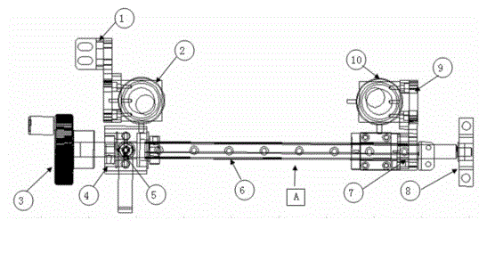
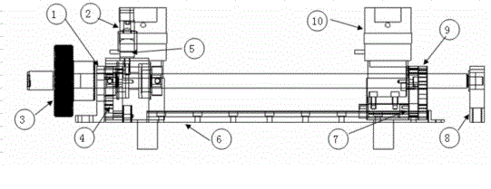
[0009] The automatic backlight assembly machine is to combine the glass and the backlight film, and the camera detection is an important part of the machine. Provide guarantee for the speed and quality of the whole machine. Directly affect work efficiency and product quality. The camera detection mechanism includes: fixed part 1 to fix the camera 2, move the camera side, hand wheel 3 to connect the workpiece 4, install 2 bearings in the cavity of the workpiece 4, install the handle 5, install the linear guide rail 6 under the workpiece, and the linear guide rail The top of the 6 is connected with the moving block 7, the camera mounting plate 9 is installed on the side, and the camera alignment is installed, and the fixed side 8 is installed at the tail end, and the bearing is installed inside. Manually rotate the hand wheel to move the camera position.

[0010] Position the camera to detect the fixed MAX point, fine-tune the camera to ensure the focal length, and move the ca...


PUM


Abstract

The invention discloses a mechanism for detecting a camera of a fully-automatic backlight assembly machine. The working principle of the mechanism is as follows: a positioning camera end is used for detecting fixed MAX points, and the camera is finely tuned for ensuring focal distance; a movable camera end is used for moving, finely tuning and detecting MAX points on the other side for ensuring the focal distance, so as to determine positions of MAK points of backlight or glass. The mechanism comprises a fixing part (1) used for fixing the camera (2), a movable camera side, a hand wheel (3), a processing part (4), a mounting handle (5), a linear guide rail (6), a movable block (7), a fixed side (8) and a camera mounting plate (9), wherein the hand wheel (3) is connected with the processing part (4); two bearings are mounted in the inner cavity of the processing part (4); the linear guide rail (6) is mounted under the processing part; the upper part of the linear guide rail (6) is connected with the movable block (7); the camera mounting plate (9) is mounted on the side surface and is used for aligning when mounting the camera; the fixed side (8) is mounted at the tail end; a bearing is arranged in the linear guide rail; the hand wheel is manually rotated to move the position of the camera.

Description

technical field [0001] The invention relates to a mechanism in a fully automatic backlight assembly machine, in particular to a camera detection mechanism. Background technique [0002] With the development of society, high requirements are put forward for the practical performance of fully automatic backlight assembly machines. There are more and more manufacturers using automatic backlight machines. The semi-automatic backlight assembly machines produced by Shenzhen "Shenkeda" company in China, and abroad There are various backlight machines produced by companies such as Panasonic and Hitachi. The existing camera detection mechanism is expensive and inconvenient to adjust, not compact and practical enough. Contents of the invention [0003] The invention aims to solve the problems of precision and mechanism adjustment performance of the camera detection mechanism in the fully automatic backlight assembly machine, and the problems of not being compact and practical enoug...

Claims


Application Information

Patent Timeline
IPC IPC(8): H04N17/00
Inventor 李忠奎邹艳秋
Owner DALIAN YISHENGDA INTELLIGENT TECH
Learn More