Belt buckle
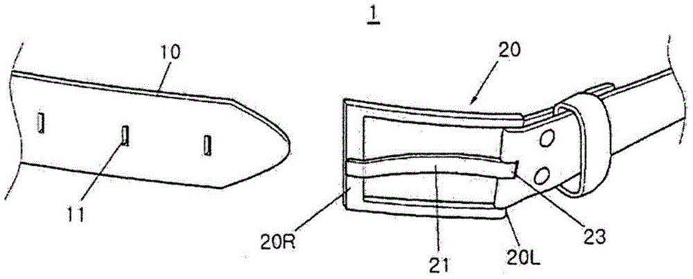
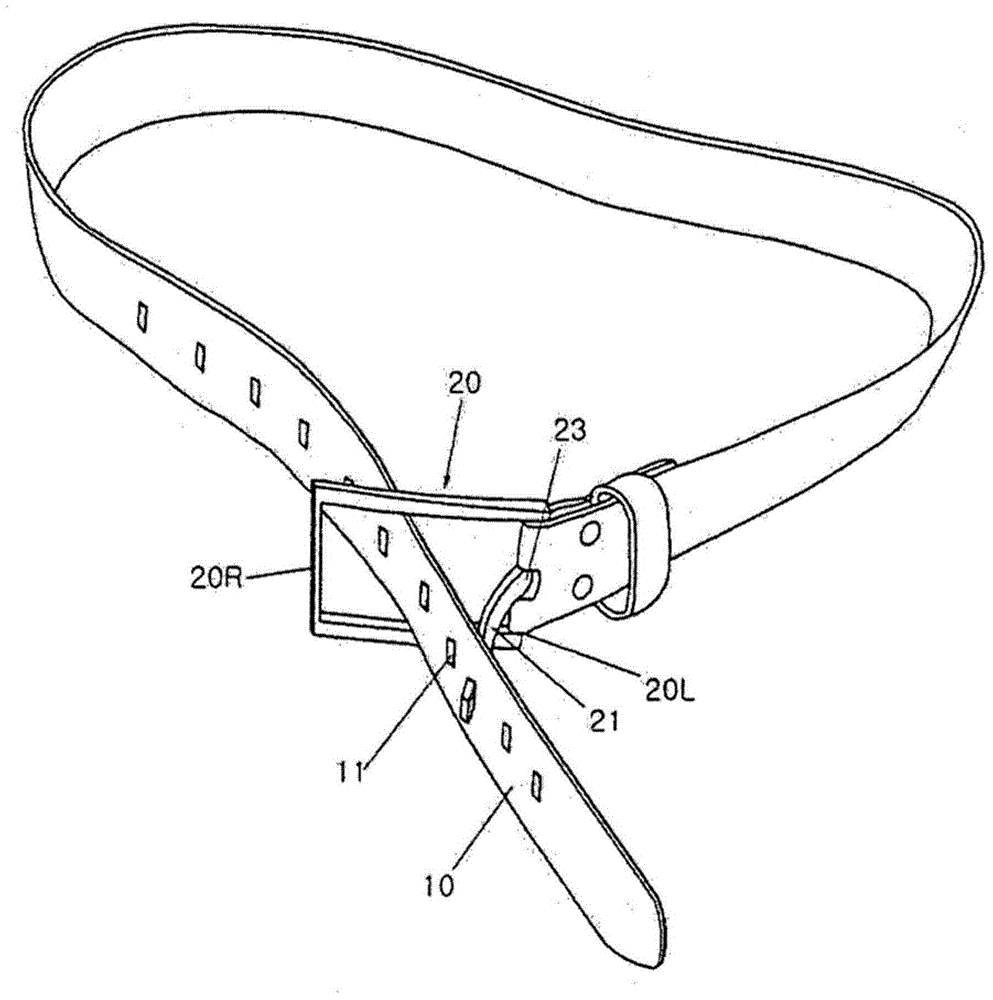
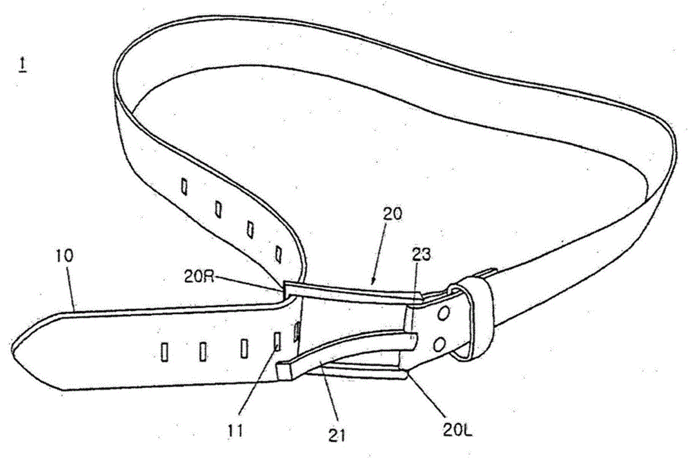
A belt and buckle technology, applied in the field of belt buckle, can solve the problems of deformation of the belt body, damage to the periphery of the hole 11, excessive pulling, etc., so as to minimize the degree of damage, reduce damage, and prevent damage. Effect
- Summary
- Abstract
- Description
- Claims
- Application Information
AI Technical Summary
Problems solved by technology
Method used
Image
Examples
no. 1 example
[0043] In the figure, Figure 4 It is a perspective view showing the belt of the first embodiment of the present invention, Figure 5 to represent Figure 4 The perspective view of the wearing belt is shown.
[0044] Such as Figure 4 As shown in the figure, the belt 100 includes a belt body 110 having a hole 111 formed in a lengthwise direction and a buckle 120 .
[0045]As mentioned above, the buckle 120 has a square frame structure, and the end of the belt body 110 is fixed to the left side frame 120L of the square frame.
[0046] The connecting pin 121 is combined with the left side frame 120L of the buckle 120 by the hinge 123, and the length of the connecting pin 121 is interfered by the right side frame 120R. Therefore, the connecting pin 121 can be combined with the left side frame 120L via the hinge 123 and rotate in front of the buckle 120 .
[0047] On the one hand, a locking portion 125 is formed at the end of the connecting pin 121 , and the distance from the...
no. 2 example
[0053] Figure 6 It is a perspective view showing the wearing process of the belt according to the second embodiment of the present invention, Figure 7 for expressing in Figure 6 The shown perspective view of the untie process in the belt wearing state, Figure 8 to represent Figure 6 The perspective view of the state where the ornament is attached to the connecting pin is shown.
[0054] Such as Figure 6 As shown, the waist belt 100 includes a waist belt body 110 and a buckle 120 fastened to a square frame at the end of the waist belt body 110 .
[0055] In the buckle 120 of the second embodiment, the connection pin 121 is combined with the right side frame 120R by means of a hinge. That is, the connecting pin 121 is connected to the right side frame 120R, which is the side where the waist belt body 110 is introduced into the buckle 120, via the hinge 123, and the end of the connecting pin 121 is interfered by the left side frame 120L. . Furthermore, the above-ment...
no. 3 example
[0063] The front end of the connecting pin of the belt buckle of the third embodiment is branched, and the ends of the branches are used to perform the same function as the locking portion described in the first and second embodiments.
[0064] In the figure, Figure 9 It is a perspective view showing the wearing process of the belt according to the third embodiment of the present invention, Figure 10 to represent Figure 9 Perspective view of the belt variant shown.
[0065] Such as Figure 9 and Figure 10 As shown, at least one branch portion 127 in a branch form is formed at the end portion of the connecting pin 121 . Figure 9 represents a structure in which two branch portions 127 are formed, Figure 10 A structure in which three branch portions are formed is shown, and the branch portion 127 extends in parallel to the terminal end direction of the connection pin 121 .
[0066] In this way, the branch portion 127 formed at the end of the connecting pin 121 is inse...
PUM
 Abstract
Description
Claims
Application Information
 - R&D
- Intellectual Property
- Life Sciences
- Materials
- Tech Scout
- Unparalleled Data Quality
- Higher Quality Content
- 60% Fewer Hallucinations
Browse by: Latest US Patents, China's latest patents, Technical Efficacy Thesaurus, Application Domain, Technology Topic, Popular Technical Reports.
© 2025 PatSnap. All rights reserved.Legal|Privacy policy|Modern Slavery Act Transparency Statement|Sitemap|About US| Contact US: help@patsnap.com


