
Mold pin for separable molding

A forming mold and separate technology, which is applied in the field of separate forming mold pins, can solve the problems of time delay in maintenance and repair, product productivity and economical decline, etc., to improve service life, improve productivity and economy, The effect of shortening maintenance time

Inactive Publication Date: 2014-03-26
韩演洙
View PDF8 Cites 2 Cited by
  • Summary
  • Abstract
  • Description
  • Claims
  • Application Information

AI Technical Summary

Problems solved by technology

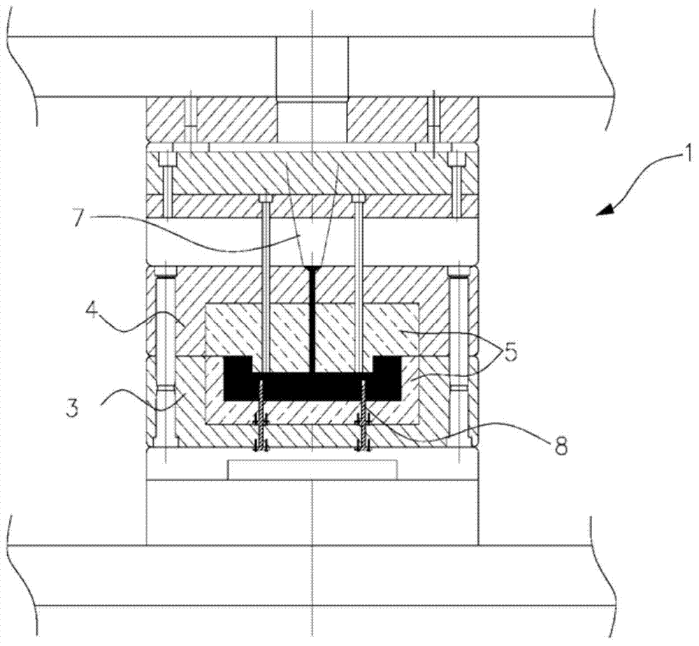
[0007] However, in the conventional mold device, in order to replace the damaged molding die pin 8, the core mold of the molding part and the peripheral mold parts constituting the mold device are disassembled one by one, and the bolts are loosened to perform replacement work. Maintenance and repair time is naturally delayed
In addition, there is a problem that the productivity and economical efficiency of products are reduced by this.

Method used


Image

  • Mold pin for separable molding
  • Mold pin for separable molding
  • Mold pin for separable molding

Examples


Embodiment Construction

[0021] The present invention will be described in detail below in conjunction with the accompanying drawings.

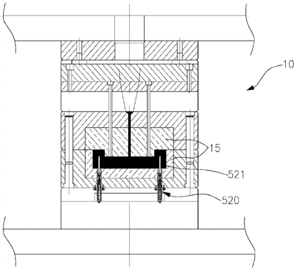
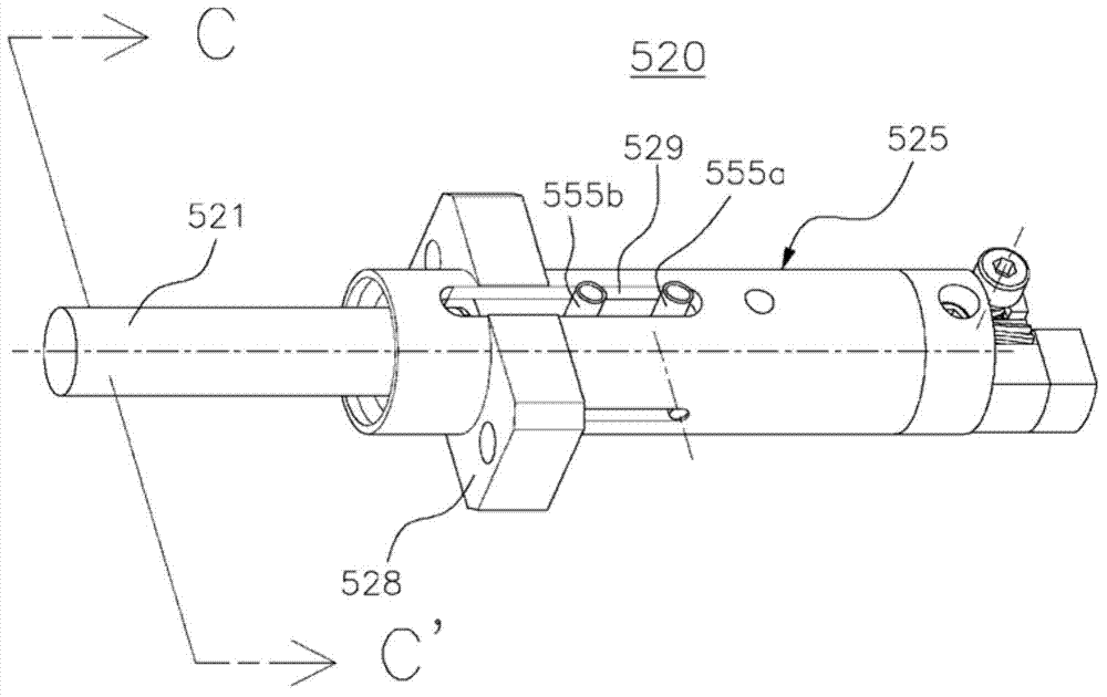
[0022] figure 2 It is a cross-sectional view of an embodiment of a molding die pin separation type assembly device suitable for a die device according to the present invention, image 3 It is an external oblique view of an embodiment of the molding die pin separation type assembly device according to the present invention. Such as figure 2 and image 3 As shown, the molding die pin separation type assembly device 520 is fixed to the molding part core mold 15 or the peripheral frame of the mold device 10 by bolting or the like. Here, the mold pin detachable assembly device 520 detachably assembles the detachable mold pin 521, so when the detachable mold pin 521 is broken, it can be easily replaced. Here, on the outer peripheral side of the main body case of the molding die pin separation type assembly device 520, there is provided a mold device coupling part 528...


PUM


Abstract

In order to provide a mold pin-separable fixing apparatus providing a structure for effective maintenance and repair of a mold pin, the present invention provides a separable mold pin, which is fixed to the mold pin-separable fixing apparatus comprising a fixing unit for performing a fixing operation from an accommodation groove, which is provided at a front end portion of a main body case having a hollow shape, in accordance with movement in front / back directions along an inner circumference of the main body case, and the separable mold pin comprises: a body which is provided so as to be inserted and arranged inside a cavity of a molding device; and a head portion, which is provided with a stepped groove that is formed so as to extend from an end portion of the body and to be inserted into the accommodation groove, thereby selectively locking by means of the fixing operation.

Description

technical field [0001] The invention relates to a separate forming mold pin, in particular to a separate forming mold pin providing a high-efficiency maintenance and repair structure. Background technique [0002] Typically a die casting or injection mold assembly comprises a core mold corresponding to the shape of the die casting or injection molding article, mold pins inside said core mold, and a number of peripheral devices for driving the core mold. [0003] figure 1 is a cross-sectional view of an existing mold setup. [0004] Such as figure 1 As shown, the mold device 1 has a forming part core mold 5 on the inside between the upper mold 3 and the lower mold 4, and a cavity corresponding to the shape of the die-casting or injection molding product is formed inside the forming part core mold 5. Here, either side of the upper mold 3 and the lower mold 4 is equipped with a movable side mold, and when the movable side mold advances and the mold is closed, the nozzle 7 an...

Claims


Application Information

Patent Timeline
Patent Type & Authority Applications(China)
IPC IPC(8): B22D17/22B29C45/17B29C45/26B29C33/74
CPCB29C45/2675B22D17/22B29C33/76B22D17/229B29C45/40
Inventor 韩演洙
Owner 韩演洙
Learn More