Inner hole sleeve pulling device

An inner hole sleeve and puller technology, which is applied to hand-held tools, manufacturing tools, etc., can solve the problems of low work efficiency, time-consuming and laborious, and difficult disassembly.

Inactive Publication Date: 2015-06-03
ACADEMY OF ARMORED FORCES ENG PLA
View PDF6 Cites 3 Cited by
  • Summary
  • Abstract
  • Description
  • Claims
  • Application Information

AI Technical Summary

Problems solved by technology

[0002] In the process of maintaining mechanical equipment, it is often necessary to disassemble bushes, sealing sleeves, bearing outer rings and other components tightly embedded in blind holes, but due to the bushings and sealing sleeves embedded in blind holes 1. The inner end face of the outer ring of the bearing is usually on the inner hole step in the inner hole. It is difficult for the existing various pullers to effectively hook the bushing, sealing sleeve, bearing outer ring embedded in the blind hole. The inner end face of the ring makes it very difficult to disassemble the bushing, sealing sleeve, and bearing outer ring embedded in the blind hole.

Method used


Image

  • Inner hole sleeve pulling device
  • Inner hole sleeve pulling device
  • Inner hole sleeve pulling device

Examples


Embodiment Construction

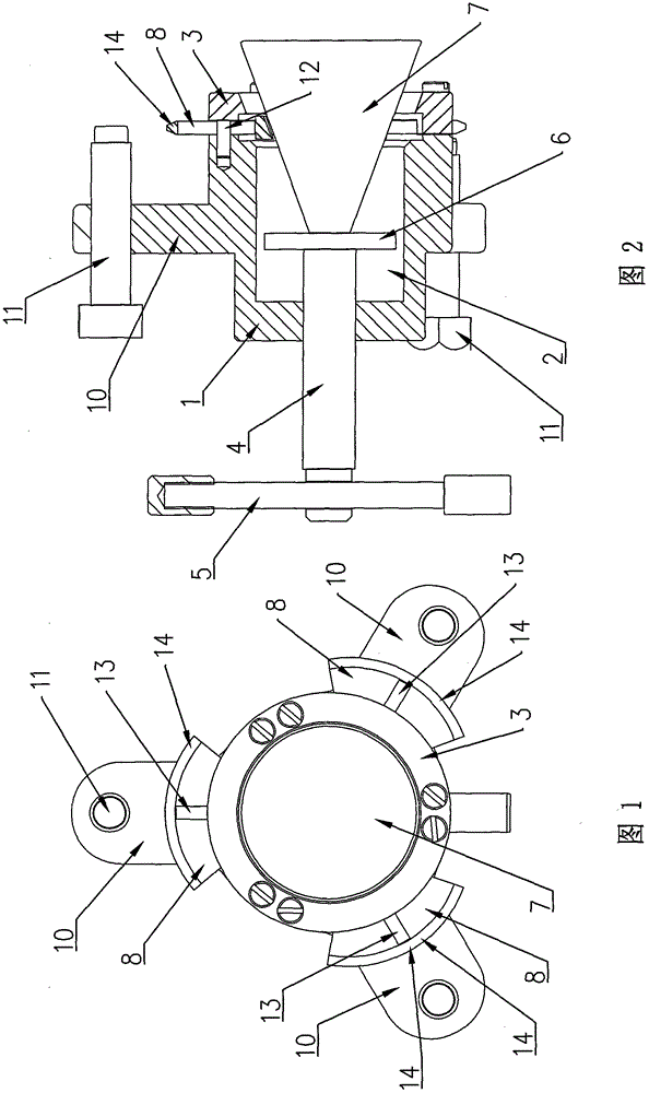
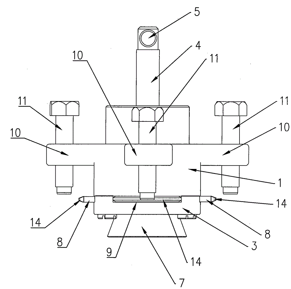
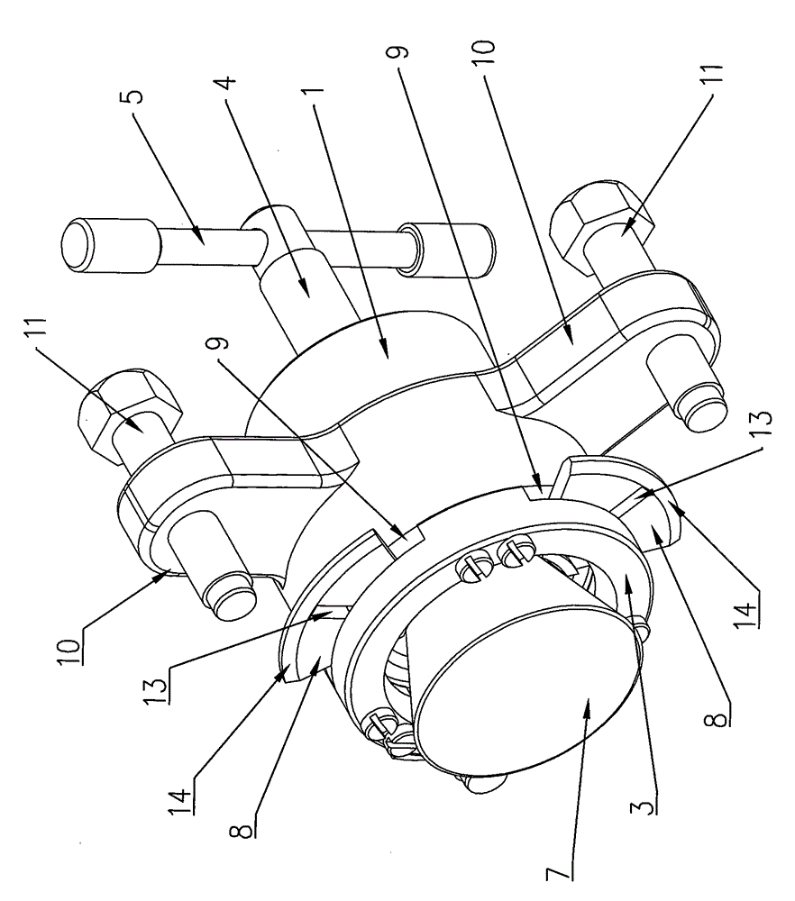
[0019] Such as figure 1 , figure 2 , image 3 with Figure 4 As shown, the inner hole sleeve pulling device of the present invention includes a cylindrical lifting base 1, the axis of the lifting base 1 is located in the front and rear horizontal direction, and the middle part of the front end face of the lifting base 1 is provided with a cylindrical shape. Cavity 2, the middle part of the outer wall of the lifting base 1 is fixedly connected to the inner end of a plurality of lifting plates 10, and the plurality of lifting plates 10 are evenly distributed around the circumferential surface of the lifting base 1, and each lifting plate The plate surfaces of 10 extend outward along the radial direction of the cylindrical lifting base 1, and each lifting plate 10 is respectively screwed with lifting bolts 11 along the front and rear horizontal directions;

[0020] An annular gland 3 is fixed on the forward end surface of the lifting base 1, and a plurality of guide grooves 9...


PUM


Abstract

An inner hole sleeve pulling device comprises a cylindrical pulling base. The axis of the pulling base is in the longitudinal and horizontal directions, a cylindrical cavity is arranged in the middle of the front end surface of the pulling base, the outer side wall of the pulling base is fixedly connected to the inner ends of a plurality of pulling plates, the pulling plate are distributed on the circumference of the pulling base in a surrounded manner, the surface of each pulling plate extends outwardly and radially, and pulling bolts are rotationally installed on the surfaces of the pulling plates in the longitudinal and horizontal directions; a round press cover is fixed to the front end surface of the pulling base, a plurality of guide grooves are radially formed in the rear end surface of the press cover and are distributed surrounding the circumference of the press cover evenly, and limiting rods are arranged in the middle of the guide grooves in the longitudinal and horizontal directions and are fixed to the front end surface of the pulling base. According to the device, a liner, a sealing sleeve and a bearing outer ring in a blind hole can be disassembled efficiently and rapidly, and the relevant parts are prevented from damage.

Description

technical field [0001] The invention relates to a device for pulling out an inner hole sleeve. Background technique [0002] In the process of maintaining mechanical equipment, it is often necessary to disassemble bushes, sealing sleeves, bearing outer rings and other components tightly embedded in blind holes, but due to the bushings and sealing sleeves embedded in blind holes 1. The inner end face of the outer ring of the bearing is usually on the inner hole step in the inner hole. It is difficult for the existing various pullers to effectively hook the bushing, sealing sleeve, bearing outer ring embedded in the blind hole. The inner end face of the ring makes it very difficult to disassemble the bushing, sealing sleeve, and bearing outer ring embedded in the blind hole. Contents of the invention [0003] The purpose of the present invention is to provide an inner hole sleeve lifting device that can efficiently and quickly remove the bushing, sealing sleeve, and bearing...

Claims


Application Information

Patent Timeline
Patent Type & Authority Applications(China)
IPC IPC(8): B25B27/02
CPCB25B27/062
Inventor 爨红亮李庆全李国强雷震爨玮李昕桦刘义乐陈玉强张建刘海云
Owner ACADEMY OF ARMORED FORCES ENG PLA
Why Eureka
Try Eureka