A rotary arm type lifting device used in a substation

A hoisting device and arm-type technology, applied in cranes, transportation and packaging, engine lubrication, etc., can solve problems such as inconvenient transportation and handling, poor stability and reliability, and long poles, so as to improve work stability and The effect of service life, increased load bearing area, and reduced bending degree

Inactive Publication Date: 2016-07-27
STATE GRID JIANGXI ELECTRIC POWER CO +1
View PDF8 Cites 0 Cited by
  • Summary
  • Abstract
  • Description
  • Claims
  • Application Information

AI Technical Summary

Problems solved by technology

[0002] When substations need to frequently replace equipment (such as isolating switches, transformers, lightning rods, etc.) due to various changes in conditions, since these equipment are installed on the frame, it is difficult and unsafe to complete it by manpower alone. Generally, it is necessary to use a crane Or hold poles for hoisting. If a crane is used for replacement, the power outage range is large and the cost is high. Some substation equipment is limited by the construction environment. In specific construction, the power outage range is often only an interval, surrounded by live equipment, so the crane cannot be used; Due to its relatively long length and heavy volume, the pole is inconvenient for transportation and handling, and the space in the substation is small, surrounded by live equipment. When the pole is used, it often cannot meet the safety distance from the live equipment. The use of the pole is subject to certain restrictions. Restrictions, a slight inclination of the pole may touch the adjacent live equipment to discharge, posing a safety hazard
When fixing the pole, the pole is usually tied against the frame with ropes. Once the rope is loose during the construction process, the pole may overturn, resulting in poor stability and reliability.

Method used


Image

  • A rotary arm type lifting device used in a substation
  • A rotary arm type lifting device used in a substation
  • A rotary arm type lifting device used in a substation

Examples


Embodiment Construction

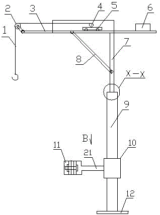
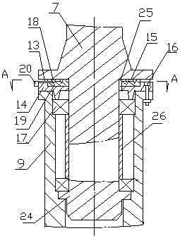
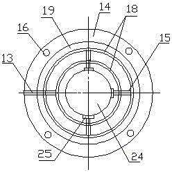
[0012] in figure 1 , figure 2 , image 3 with Figure 4 Wherein, the boom-type lifting device used in the substation includes a rotating column 7, a column 9, a beam 3, a drum 4, and a mobile trolley 5. The beam is fixed on the rotating column, and one end of the beam is provided with a runner 2 (pulley) , The other end is provided with a counterweight 6, the mobile trolley is set on the cross beam 3, the reel 4 is set on the mobile trolley 5, a diagonal brace 8 is set between the cross beam and the rotating column, and the rope 1 on the reel is Hook and go around the runner, the lower end of the column is provided with a rotating sleeve 10, the rotating sleeve is connected to the movable hoop 11 through the connecting plate 21, the column and the movable hoop are fixed to the fixing member 23 (such as The lower end of the column is provided with a base 12 on the electric pole, cement column). The movable hoop can fix the column when clamped. The connecting shaft 24 at the low...


PUM


Abstract

The invention discloses a rotating arm type hoisting device for a transformer substation. The rotating arm type hoisting device comprises a rotary column (7), a stand column (9), a cross beam (3), a coiling block (4) and a moving trolley (5), wherein the cross beam is fixed on the stand column; a rotating wheel (2) is arranged at one end of the cross beam, and a balancing weight (6) is arranged at the other end of the cross beam; the moving trolley is arranged on the cross beam; the coiling block is arranged on the moving trolley; a rope on the coiling block winds the rotating wheel; a rotary sleeve (10) is arranged at the lower end of the stand column; a connecting shaft (24) at the lower end of the rotary column enters the upper end of the stand column through plane bearings (17) arranged at an interval and is movably connected with the stand column; a gland (14) is fixedly arranged at the upper end of the stand column; a wear-resisting plate (3) is arranged in the gland; annular oil grooves (18) are formed in the upper surface of the wear-resisting plate at intervals; an oil through groove (15) and an oil injection hole (13) are formed between the annular oil grooves. The rotating arm type hoisting device disclosed by the invention enables the rotary column to be flexibly rotated on the stand column, is compact and simple in structure, convenient to use and maintain, free of limitation in use generally, safe and reliable.

Description

Technical field [0001] The invention relates to hoisting equipment, in particular to a hoisting device used for substation installation and replacement of electric equipment. Background technique [0002] When substations need to frequently replace equipment (such as isolating switches, transformers, lightning rods, etc.) due to changes in various conditions, these equipment are installed on the frame, which is difficult and unsafe to complete by manpower. Generally, cranes are required. Or use a pole for hoisting. If a crane is used to replace it, the power outage range is large and the cost is high. Some substation equipment is restricted by the construction environment. In specific construction, the power outage range is often only an interval, surrounded by live equipment, so the crane cannot be used; Due to its relatively long length, heavy volume, inconvenient transportation and handling, and the small space in the substation, the poles are surrounded by live equipment. The...

Claims


Application Information

Patent Timeline
Patent Type & Authority Patents(China)
IPC IPC(8): B66C23/16B66C23/62F16N1/00
CPCB66C23/027B66C23/166B66C23/62B66C2700/0385F16N1/00
Inventor 叶国军陈琳
Owner STATE GRID JIANGXI ELECTRIC POWER CO
Why Eureka
Try Eureka