Reinforcement cage for cast-in-place pile with oversized tip

A technology of steel skeleton and cast-in-place piles, applied in sheet pile wall, construction, infrastructure engineering, etc., can solve the problems of inability to increase the diameter of the pile bottom and the difficulty of guaranteeing the size of the pile bottom, so as to improve the overall seismic capacity and load bearing capacity. The effect of simple force and mechanical structure

Active Publication Date: 2011-02-09
中国安能集团第三工程局有限公司
View PDF8 Cites 0 Cited by
  • Summary
  • Abstract
  • Description
  • Claims
  • Application Information

AI Technical Summary

Problems solved by technology

It is also difficult to guarantee the size of the pile bottom, and it is not possible to add a reinforcement cage to form a large-diameter pile bottom of reinforced concrete

Method used


Image

  • Reinforcement cage for cast-in-place pile with oversized tip
  • Reinforcement cage for cast-in-place pile with oversized tip
  • Reinforcement cage for cast-in-place pile with oversized tip

Examples


Embodiment Construction

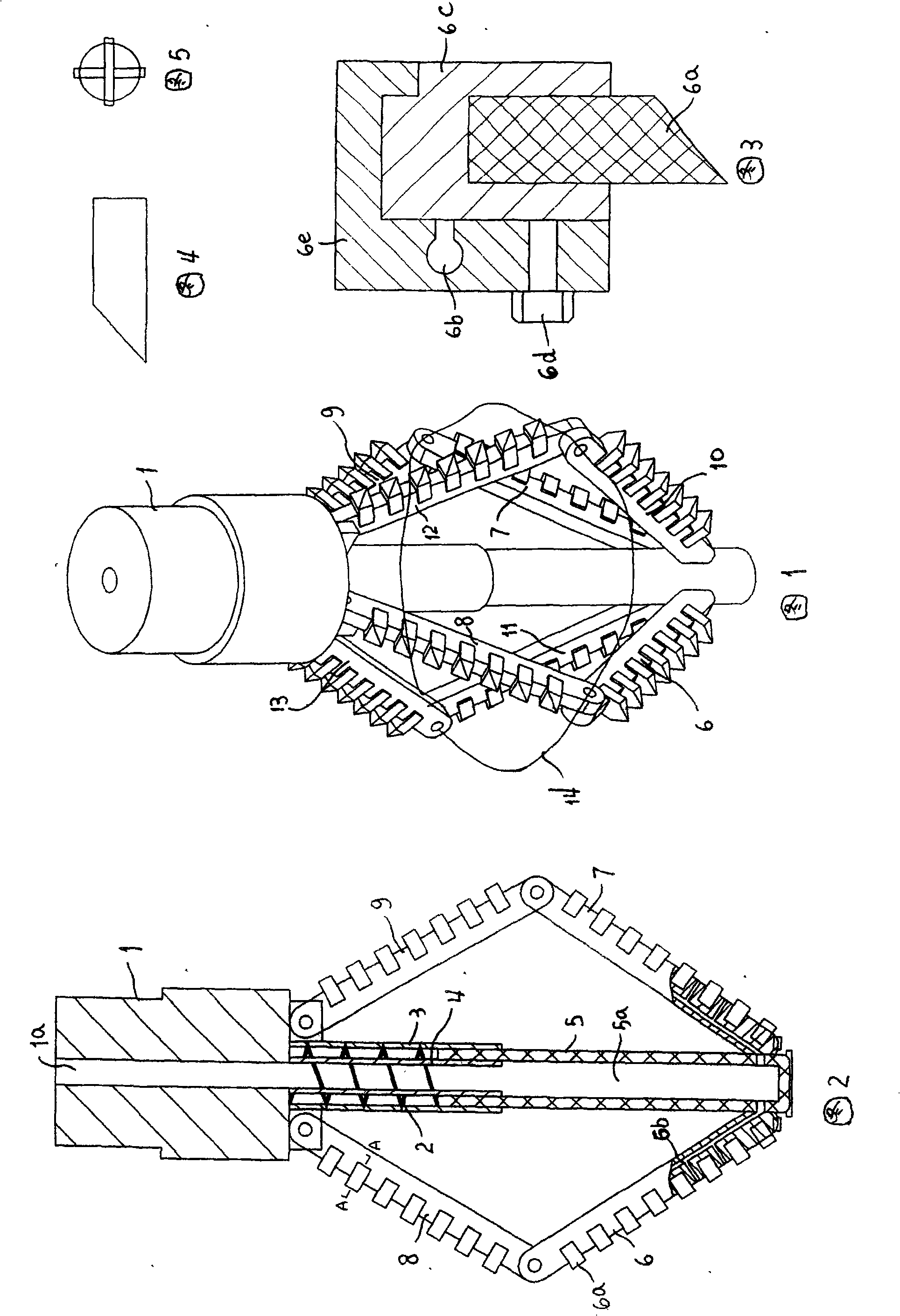
[0056] A method for constructing cast-in-situ piles with super-diameter reaming at the ends of machine drills, characterized in that: the following steps are carried out:

[0057] a) Use conventional pile drilling rigs to construct to the predetermined reaming depth;

[0058] b) Replace the reaming drill bit to carry out the construction of the reaming section, so that the bottom of the pile forms a cylinder or cone with a diameter of 2 to 4 times the diameter of the pile body;

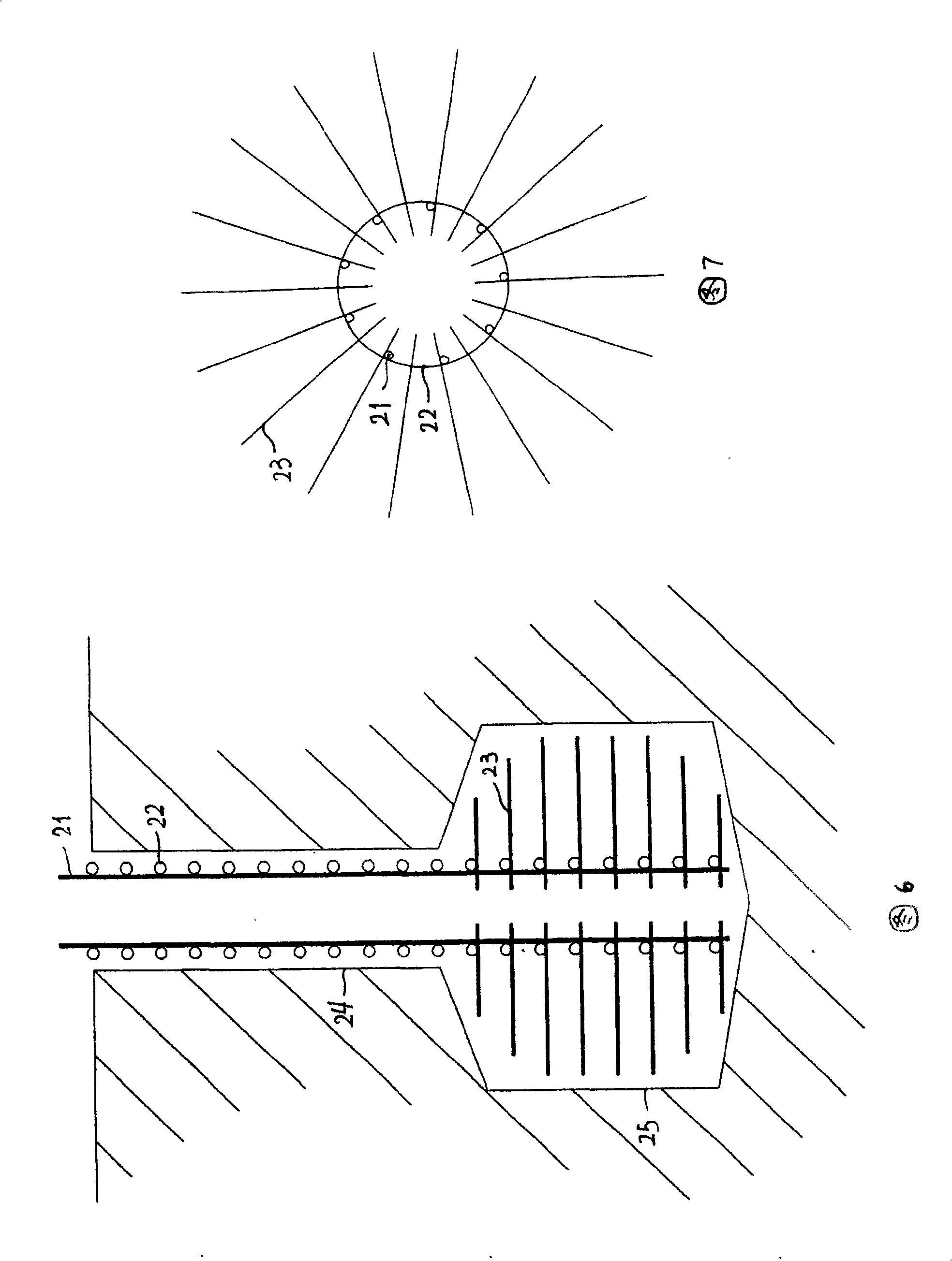
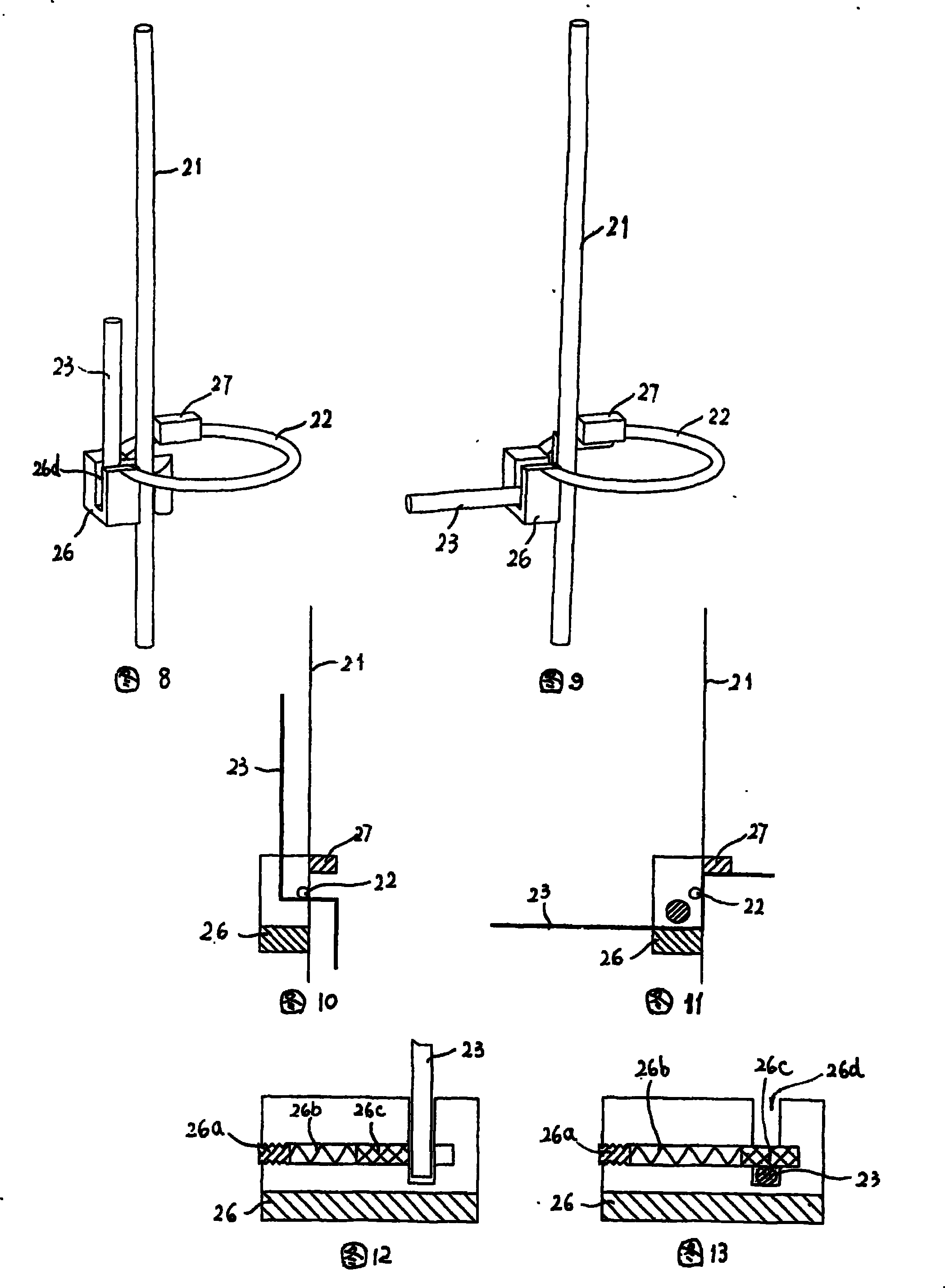
[0059] c) Use gravity or external force to lower the reinforcement cage;

[0060] d) Pouring concrete to form cast-in-place piles.

[0061] The detailed construction steps of the present invention are as follows:

[0062] The construction process is leveling the site → laying the pile position line and re-testing → drilling rig in place → correcting the centering and sag of the drill pipe → drilling → slag removal → soil removal → placing the steel hole protection pipe at the orifice → measuring the...


PUM


Abstract

The invention discloses a reinforcement cage for a cast-in-place pile with an oversized tip, which comprises a plurality of longitudinal reinforcing steel bars distributed along the same periphery, and a plurality of annular reinforcing steel bars distributed along the vertical direction and connected with the longitudinal reinforcing steel bars; the longitudinal reinforcing steel bars positionedin a hole enlarging section of the cast-in-place pile are evenly distributed with radial divergence reinforcing steel bars; each divergence reinforcing steel bar is formed by bending a straight reinforcing steel bar to have an upper vertical section, a horizontal section and a lower vertical section; the divergence reinforcing steel bars are hinged to the longitudinal reinforcing steel bars or the annular reinforcing steel bars; the longitudinal reinforcing steel bars are provided with a clamping positioning mechanism respectively corresponding to each divergence reinforcing steel bar; a positioning clamp and a positioning plate are respectively welded on the outside and the inside of each longitudinal reinforcing steel bar; the front side of the positioning clamp positioned on the lower part is provided with an opening groove into which each divergence reinforcing steel bar is clamped; the lateral surface of the positioning clamp is provided with a blind hole which passes through theopening groove and extends outwards; and a bolt, a spring and an adjusting screw are orderly arranged in the blind hole from inside to outside. A hole enlarging pile with the oversized tip formed by the invention has the advantages of large stressed area on pile bottom, high load bearing capacity of a single pile and strong seismic capacity of the bottom of the single pile.

Description

[0001] This application is a divisional application of patent application number 200710049584.1 (name of invention: construction method of cast-in-place pile with over-diameter reaming at the end of machine drill and its special equipment; application date: July 23, 2007). technical field [0002] The invention relates to a construction method of reinforced concrete cast-in-place piles, in particular to a construction method and special tools for cast-in-situ piles with large-diameter pile foundations, and especially relates to the geological conditions of high-rise and ultra-high-rise civil construction projects with non-bedrock as the bearing layer Under the premise of increasing the load-bearing area at the bottom of the pile foundation, the single pile bearing capacity is doubled without changing the pile diameter and pile depth, and the construction technology and special equipment for improving the overall earthquake resistance. Background technique [0003] At present,...

Claims


Application Information

Patent Timeline
Patent Type & Authority Patents(China)
IPC IPC(8): E02D5/44
Inventor 刘俊君詹登民张仕超
Owner 中国安能集团第三工程局有限公司
Why Eureka
Try Eureka