Three-axis positioning system of numerical control gantry flange drilling machine

A gantry flange and shaft positioning technology, which is applied to large fixed members, metal processing machinery parts, maintenance and safety accessories, etc., can solve the problems of extended processing time, small force, iron filings and slag entry, etc., to reduce sliding The effect of reducing energy consumption, increasing service life, and reducing overall self-weight

Pending Publication Date: 2022-04-12
TIANJIN BAOLAI PRECISION MACHINERY
View PDF0 Cites 0 Cited by
  • Summary
  • Abstract
  • Description
  • Claims
  • Application Information

AI Technical Summary

Problems solved by technology

[0002] In the prior art, the sliding connection contact points of the X-axis sliding seat of the gantry flange drilling machine and the X-axis cantilever beam are mostly on the same plane. In the above design, the X-axis sliding seat only serves as the Z-axis cantilever support function. It bears less force, and a tool magazine is fixed at one end of the X-axis cantilever beam. Every time a tool is changed, the X-axis sliding seat needs to slide to the position of the tool magazine to change the tool, and then the X-axis sliding seat slides to the predetermined processing position. Provide guidance for the Z-axis cantilever lifting, this structure makes the X-axis slide seat do not need to bear excessive load, but in order to improve processing efficiency, the tool magazine of the gantry drilling machine can also be transferred to the X-axis slide seat, which can avoid the X-axis slide seat The problem of reciprocating tool change and prolonging the processing time, however, this improvement will inevitably increase the bearing load of the X-axis slide seat. In the prior art, the sliding connection structure between the X-axis slide seat and the X-axis cantilever beam located on the same plane is difficult to bear the Z The overall weight of the axis cantilever and tool magazine
[0003] In addition, the gantry flange drilling machine in the prior art has a single Y-axis guide beam structure and no auger, and often only has the sliding support and power supply functions of the X-axis cantilever beam, and does not have the cleaning of drilling debris. Cleaning function
However, most of the gantry flange drilling machines in the prior art collect and clean debris manually, and it is difficult to realize the automatic debris cleaning function. Once the manual cleaning is not in place or the cleaning is not timely, it is easy to cause iron chips and debris to enter the Y-axis guide The sliding connection between the beam and the X-axis cantilever beam will cause the accuracy of the drilling machine to drop, and in severe cases, the X-axis cantilever beam will be stuck

Method used


Image

  • Three-axis positioning system of numerical control gantry flange drilling machine
  • Three-axis positioning system of numerical control gantry flange drilling machine
  • Three-axis positioning system of numerical control gantry flange drilling machine

Examples


Embodiment Construction

[0037] In order to further understand the content, characteristics and effects of the present invention, the following examples are given, and detailed descriptions are given below with reference to the accompanying drawings. It should be noted that this embodiment is descriptive, not restrictive, and cannot thereby limit the protection scope of the present invention.

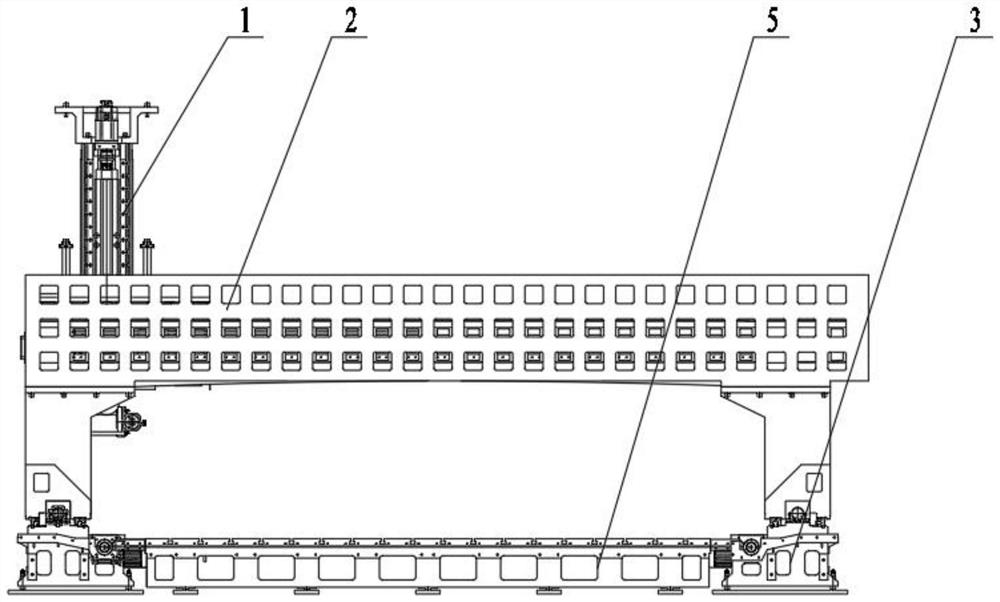
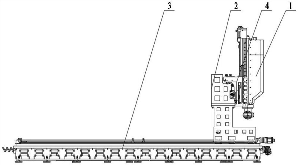
[0038]A three-axis positioning system of a CNC gantry flange drilling machine, the three-axis positioning system straddles the processing platform 5 of the CNC gantry flange drilling machine, and the three-axis positioning system includes:

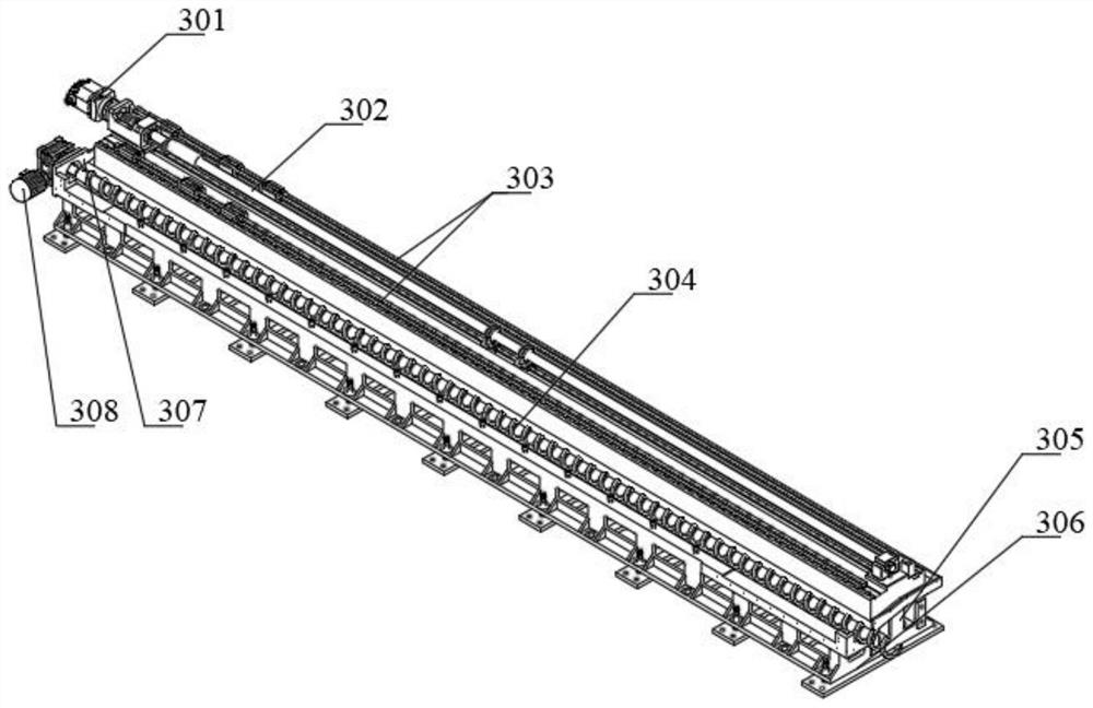
[0039] Y-axis guide beam 3: The Y-axis guide beam is symmetrically arranged on both sides of the processing platform. The Y-axis guide beam is close to the top surface of the side of the processing platform. On the top surface of the guide beam away from the processing platform, there is an upwardly protruding guide beam first step 305; the middle part of the top surface of...


PUM


Abstract

The invention discloses a three-axis positioning system of a numerical control gantry flange drilling machine, the three-axis positioning system is arranged on a machining platform of the numerical control gantry flange drilling machine in a spanning manner, the three-axis positioning system comprises Y-axis guide beams symmetrically arranged on two sides of the machining platform, and an X-axis cantilever beam connected with an X-axis sliding seat in a sliding manner along the horizontal transverse direction; the bottom of the X-axis cantilever beam is connected to the Y-axis guide beam in a sliding mode in the horizontal longitudinal direction, the back face of the X-axis sliding base is connected to the X-axis cantilever beam in a horizontal sliding mode, the front face of the X-axis sliding base is connected with the Z-axis cantilever in a lifting sliding guiding mode, and the X-axis sliding base is supported by the three-axis positioning system in a stepped sliding mode at the planes and the depth positions in different directions. The Y-axis guide beam is arranged on the X-axis cantilever beam to improve the sliding bearing capacity of the X-axis sliding seat on the X-axis cantilever beam, the Y-axis guide beam integrates the sliding guide function of the X-axis cantilever beam, the power support function of the X-axis cantilever beam and the chip removal and slag discharge function, the structure is simple, and implementation is easy.

Description

technical field [0001] The invention relates to the technical field of drilling machinery, in particular to a three-axis positioning system of a numerically controlled gantry flange drilling machine. Background technique [0002] In the prior art, the sliding connection contact points of the X-axis sliding seat of the gantry flange drilling machine and the X-axis cantilever beam are mostly on the same plane. In the above design, the X-axis sliding seat only serves as the Z-axis cantilever support function. It bears less force, and a tool magazine is fixed at one end of the X-axis cantilever beam. Every time a tool is changed, the X-axis sliding seat needs to slide to the position of the tool magazine to change the tool, and then the X-axis sliding seat slides to the predetermined processing position. Provide guidance for the Z-axis cantilever lifting, this structure makes the X-axis slide seat do not need to bear excessive load, but in order to improve processing efficiency,...

Claims


Application Information

Patent Timeline
IPC IPC(8): B23Q1/01B23Q5/28B23Q11/00
Inventor 崔超崔越崔文来崔建涛崔雅臣张涛李绍功李绍德梁东坡王振锋崔艳鹏
Owner TIANJIN BAOLAI PRECISION MACHINERY
Why Eureka
Try Eureka