Numerical control gate boring-milling machine high-speed main spindle clamp tool resetting mechanism

A technology of high-speed spindle and reset mechanism, which is applied in the direction of clamping, positioning devices, metal processing machinery parts, etc., can solve the problem of high force on the thrust bearing at the tail of the spindle, and achieve high-speed re-cutting and reduce the force load.

Active Publication Date: 2009-07-08
通用技术齐齐哈尔二机床有限责任公司
View PDF0 Cites 0 Cited by
  • Summary
  • Abstract
  • Description
  • Claims
  • Application Information

AI Technical Summary

Problems solved by technology

[0004] In order to overcome the problem that the main shaft rotates and is always in the state of clamping the tool when the machine tool is working, resulting in a large force on the thrust bearing at the end of the main shaft. In the rotating state, the loosening device and the spindle sleeve are separated to ensure that the thrust bearing does not bear the influence of cutting force and clamping force when the spindle rotates, so as to realize the high-speed re-cutting requirements of the CNC gantry boring and milling machine

Method used


Image

  • Numerical control gate boring-milling machine high-speed main spindle clamp tool resetting mechanism
  • Numerical control gate boring-milling machine high-speed main spindle clamp tool resetting mechanism
  • Numerical control gate boring-milling machine high-speed main spindle clamp tool resetting mechanism

Examples


Embodiment Construction

[0014] Below in conjunction with accompanying drawing, the utility model is further described:

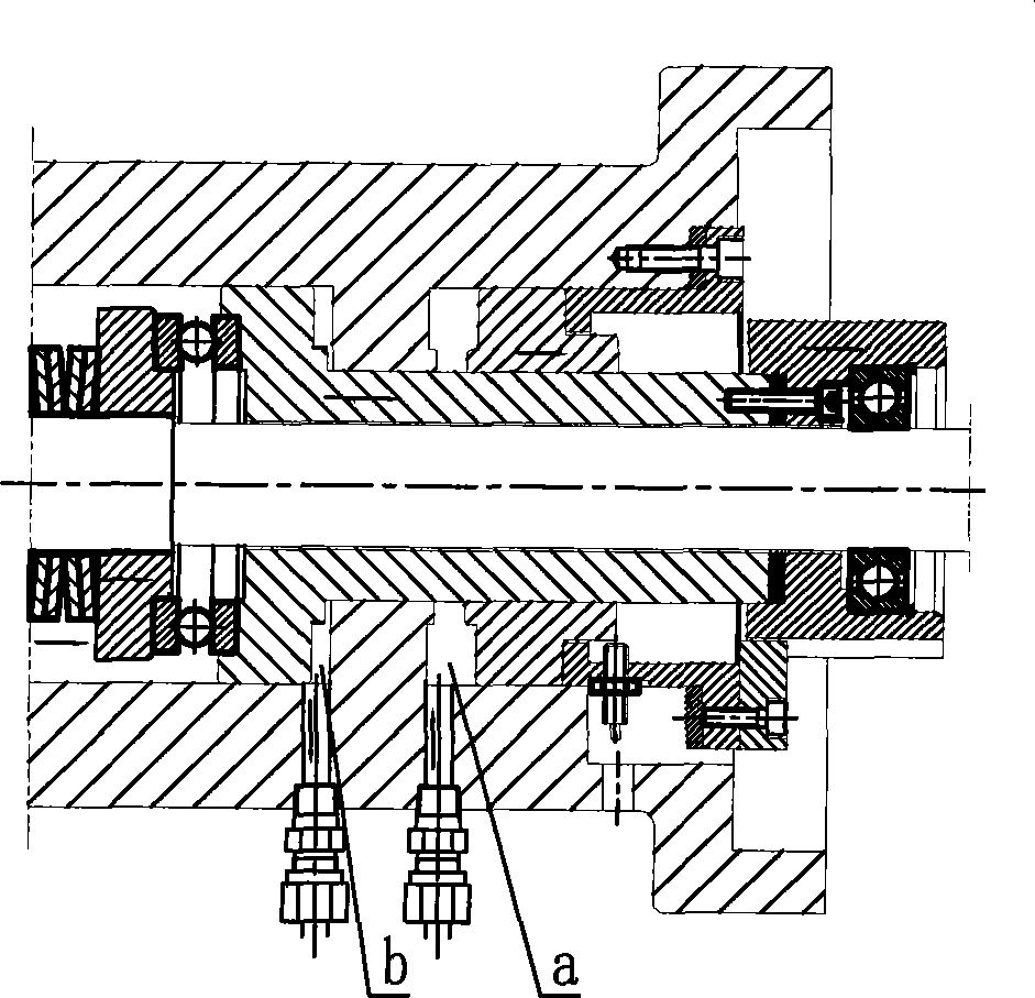
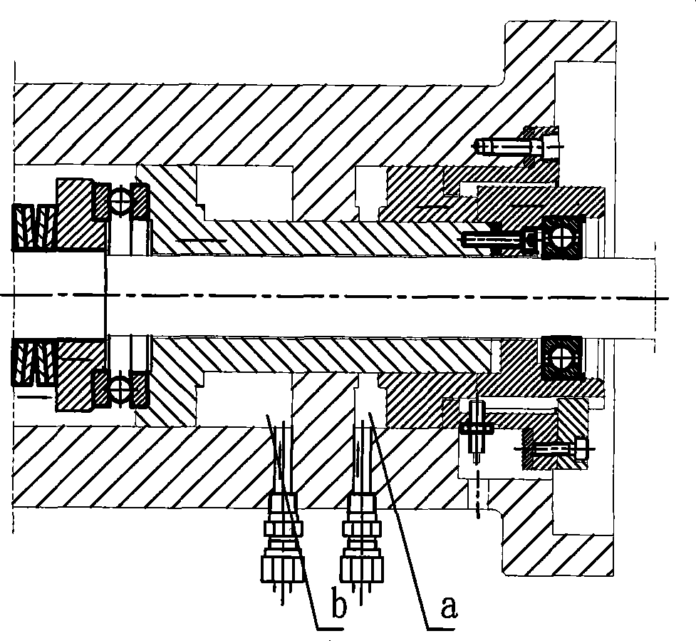
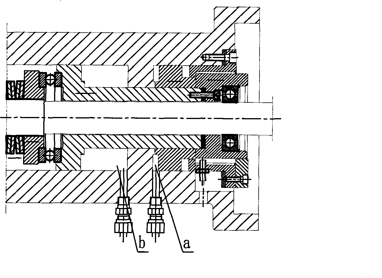
[0015] attached by Figure 4 - attached Figure 6 As shown, the high-speed spindle tool clamping reset mechanism of the CNC gantry boring and milling machine is improved on the basis of the original mechanism, and the oil chamber c for realizing the reset action is added, so that there is a tool clamping reset gap X between the push rod 8 and the spindle sleeve 7, The value range of X is between 1mm and 3mm, which is sufficient to ensure that the push rod 8 is separated from the main shaft sleeve 7, and if it is too large, the movement stroke of the tool release device will be increased. Current institutions such as Figure 4 As shown, it mainly includes oil cylinder 1, new piston rod 2 and piston 3, the left end of oil cylinder 1 is fixed with connecting sleeve 5, and the connecting sleeve 5 is fixed on the headstock of the ram; the inner steps of connecting sleeve 5, oil cylind...


PUM


Abstract

The present invention relates to a high-speed main shaft cutter holding rest mechanism of digital control plano-boring and milling machine. The invention mainly settles the force bearing condition of thrust bearing at tail part of principal axis for satisfying the requirement of high-speed recutting of numerical control machine tool. The invention is characterized in that the left end of oil cylinder (1) is fixed with a connecting sleeve (5). Oil cylinders (a, b, c) are provided among the connecting sleeve (5), the oil cylinder (1), a new piston rod (2) and a piston (3). The left end of new piston rod (2) is connected with a push rod (8) through an axial force rolling pair (6). A radial centering rolling pair (10) is installed between the rod diameter of push rod (8) and the new piston rod (2). An axial clearance X is provided between the left end face of push rod (8) and a main shaft sleeve (7). The mechanism can realize the separation of transmission device and the main shaft sleeve in working state and guarantee that the rolling pair is not affected by cutting force and cutter clamping force in operation thereby realizing the requirement of high-speed recutting of digital control plano-boring and milling machine.

Description

technical field [0001] The invention relates to a tool clamping mechanism for a spindle of a CNC gantry boring and milling machine, in particular to a reset mechanism for a high speed spindle of a CNC moving beam gantry boring and milling machine. Background technique [0002] CNC moving beam gantry boring and milling machine is mainly used for multi-station machining of large parts. It is mainly composed of a bed, a gantry, a sliding seat, a beam, a sliding crate, a spindle box, and a square ram. The bed is fixed on the foundation, the left and right sliding seats are placed on the bed, the left and right columns are respectively fixed on the sliding seats, and the left and right columns are connected together on the top surface of the columns through the connecting beam to form a closed gantry frame. The gantry moves longitudinally along the guide rail of the bed, the sliding crate moves laterally along the beam guide rail, the beam moves vertically along the vertical gui...

Claims


Application Information

Patent Timeline
IPC IPC(8): B23Q3/16
Inventor 曲波孟秋姜明程凤兰姜崇民王哲元
Owner 通用技术齐齐哈尔二机床有限责任公司
Why Eureka
Try Eureka