An Improved Installation Method of Flash Converting Furnace

An installation method and blowing furnace technology, which are applied in the processing of building materials, construction, building structure, etc., can solve the problems of large space occupation of scaffolding, complicated preparation work, and increase the cost of mechanical work, so as to reduce the construction cost of the project. , The effect of reducing the use of mechanical shifts and shortening the construction cycle

Active Publication Date: 2016-09-28
MCC5 GROUP SHANGHAI CORPORATION LIMITED
View PDF9 Cites 0 Cited by
  • Summary
  • Abstract
  • Description
  • Claims
  • Application Information

AI Technical Summary

Problems solved by technology

[0004] The known disadvantages of the above two methods: the first method needs to set up a full house of scaffolding in sections and arrange multi-layer operating platforms. The height of the furnace body is generally about 20-24m, so it needs to be erected in multiple layers, and springboards and protective nets are arranged on each platform, and limited by the installation process of the furnace body and the influence of the component reverse passage, first the sedimentation tank is constructed, and then the reaction tower and The construction of the ascending flue; the use of the maintenance crane in the factory building. Therefore, the maintenance crane in the workshop is the main tool for unloading, transporting and installing all the components of the furnace body. Therefore, the use of the maintenance crane in the factory building requires a reserve from the furnace bottom The hoisting space to the bottom of the furnace, the inter-column support of the multi-layer platforms in the hoisting space (take this project as an example, 11.76m platform, 17m platform, 23m platform, 28.4m platform, 22-23 line multi-axis spacing need to be reserved) The beam and platform system cannot be constructed and must be reserved for the furnace body construction, which will bring additional burdens and safety hazards in the installation process to the overall installation of the plant structure. Difficulties in transportation and installation of structural parts; the erection of scaffolding in large-scale sub-processes (installation of sedimentation tank first, reaction tower and ascending flue installation) also takes up too much space (affecting the construction of the plant structure in the furnace area), and the number of scaffolding used is too large , multi-platform layout, the use of multiple springboards and protective nets have a large number of hidden dangers in production safety, which brings additional management costs to on-site engineering management
[0005] The second method is to arrange two truck cranes on both sides of the sedimentation tank of the furnace body (the slag outlet side and the waste heat boiler side of the flue outlet) to arrange a hoisting sedimentation tank in the early stage, and to arrange two separate ascending flue and reaction towers in the later stage. For hoisting, this scheme also needs to set up large-scale full-scale scaffolding in different procedures. The use of truck cranes needs to occupy the space of the structural platform around the furnace body. A large number of platforms and supporting main beams between columns are reserved for the later construction of the plant structure and the closure of the plant. Additional construction costs and management costs, and the use of a large number of mechanical shifts for truck cranes will add a lot of mechanical shift costs to the overall project construction
[0006] Therefore, there are above-mentioned inconveniences and problems in the known blowing furnace installation method

Method used


Image

  • An Improved Installation Method of Flash Converting Furnace
  • An Improved Installation Method of Flash Converting Furnace
  • An Improved Installation Method of Flash Converting Furnace

Examples


Embodiment Construction

[0038] The present invention will be further described below in conjunction with embodiment and accompanying drawing.

[0039] An improved flash converting furnace installation method is characterized in that it comprises the following steps:

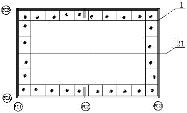
[0040] a. Set the temporary main lifting device for the furnace body components to be transported back to the furnace body

[0041] figure 1 The steel platform is used for furnace body installation. The steel platform used in this measure is the supporting steel platform for the official use of the furnace body. Before the installation of the furnace body, the first construction is re-measurement of the center line of the furnace bottom foundation, re-measurement of the foundation elevation, and installation of the bottom beam in place. The construction provides a stable and safe working platform, which is convenient for the construction personnel to install and install the skeleton columns of the furnace body and the side wall of the ...


PUM


Abstract

The invention discloses an improved installation method of a flash converting furnace. The improved installation method is characterized by comprising the following steps: a, setting a main temporary hoisting device for transshipping a furnace body component to a furnace body inside; b, providing a temporary fixing measure for a framework upright post of the side wall of the furnace body, a framework and a furnace shell plate; c, setting the layout position and method of beams of unloading and transporting, and hoisting equipment of the furnace body component; d, setting an assembling method of a reaction tower and a lifting gas flue and e, setting the temporary fixing measure of the framework upright post of the side wall of the furnace body and a furnace wall structure. The improved installation method of the flash converting furnace has the following advantages: the installation method does not use a lot of scaffolds and temporary hoisting measures for furnace body installation, so that the control precision is greatly improved, the construction cycle is largely reduced and the machine-team use is decreased, and the project construction cost is reduced.

Description

technical field [0001] The invention relates to a blowing furnace installation method, in particular, an improved flash blowing furnace installation method which improves the installation accuracy and shortens the construction period. Background technique [0002] The blowing operation is an indispensable operation in the pyrometallurgy process. The air is blown into the copper matte melt and oxidizes with the iron and sulfur in the copper matte melt to release heat, and the self-heating blowing is maintained. After the slagging period And the operation of the copper-making period produces blister copper. At present, with the rapid development of the national economy, the process of industrialization has been significantly accelerated, especially the proportion of heavy industrial projects in national construction has increased year by year. In many fields such as heavy industrial projects, according to the needs of production technology, steel structure frame beams are wid...

Claims


Application Information

Patent Timeline
Patent Type & Authority Patents(China)
IPC IPC(8): E04G21/00
Inventor 高文建聂丁未卓望雍代文唐益辉代克维
Owner MCC5 GROUP SHANGHAI CORPORATION LIMITED
Why Eureka
Try Eureka