

Illumination LED lamp
A technology of LED lights and LED light sources, applied in lighting devices, lighting and heating equipment, cooling/heating devices of lighting devices, etc., can solve the problems of failure of the whole lamp, aging and failure of driving components, etc., so as to achieve less failure, prolong life, The effect of improving heat dissipation efficiency
- Summary
- Abstract
- Description
- Claims
- Application Information
AI Technical Summary
Problems solved by technology
Method used
Image

Examples
Embodiment Construction
[0021] The present invention will be further described in detail below in conjunction with the accompanying drawings and specific embodiments.
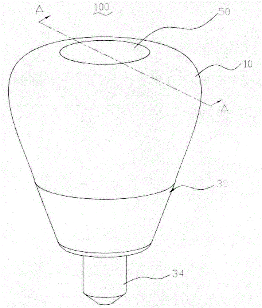
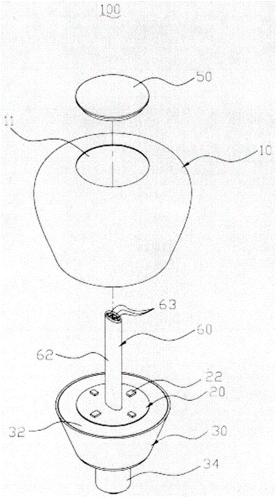
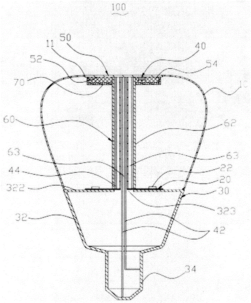
[0022] Please see figure 1 and image 3 , the lighting LED lamp 100 includes a lampshade 10 , an LED light source substrate 20 , a lamp body 30 , a set of driving electronic components 40 , a heat dissipation cover 50 , a connecting column 60 and a reflective layer 70 . The lampshade 10 is disposed on the LED light source substrate 20 . The LED light source substrate 20 is disposed on the top surface of the lamp body 30 . The group of driving electronic components 40 is disposed under the heat dissipation cover 50 . The heat dissipation cover 50 is fixed on the lampshade 10 . One end of the connecting column 60 is connected to the lamp body 30 , and the other end is connected to the heat dissipation cover 50 . The reflective layer 70 is attached outside the group of driving electronic components 40 corresponding to the LED light ...
PUM
 Abstract
Description
Claims
Application Information