Microwave oven and exciter for microwave oven

A microwave oven and exciter technology, which is applied in the field of microwave ovens, can solve the problems that microwave power cannot be effectively suppressed, the transmission efficiency of exciters is affected, and the semiconductor microwave source is easily damaged, so as to reduce reflected power, expand radiation range, and improve transmission. The effect of efficiency

Active Publication Date: 2015-06-03
GUANGDONG MIDEA KITCHEN APPLIANCES MFG CO LTD +1
View PDF6 Cites 13 Cited by
  • Summary
  • Abstract
  • Description
  • Claims
  • Application Information

AI Technical Summary

Problems solved by technology

[0002] At present, the exciter mainly used in microwave ovens is a structure in which the probe or antenna is directly inserted into the rectangular waveguide box. The exciter with this structure cannot effectively suppress the reflection of microwave power, which affects the transmission efficiency of the exciter.
Moreover, when this structure is applied to a semiconductor microwave oven, it is easy to damage the semiconductor microwave source.

Method used


Image

  • Microwave oven and exciter for microwave oven
  • Microwave oven and exciter for microwave oven
  • Microwave oven and exciter for microwave oven

Examples


Embodiment 1

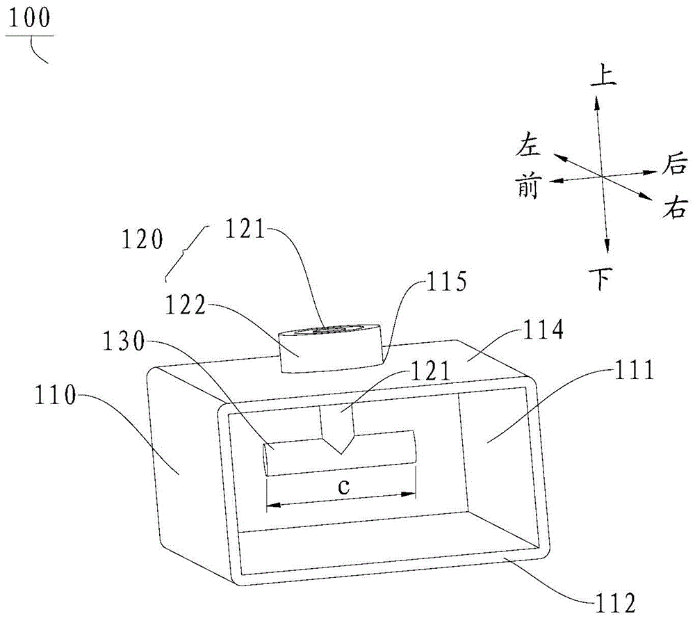
[0058] Such as image 3 , Figure 4 As shown, in this embodiment, there is one antenna rod 130 and is vertically connected to the lower end of the inner conductor 121 of the coaxial connector 120 . It should be noted that the angle between the central axis of the antenna rod 130 and the plane where the open end 112 of the waveguide box 110 is located can be determined according to the microwave frequency, for example, in image 3 In the example shown, the central axis of the antenna rod 130 is parallel to the plane where the open end 112 of the waveguide box 110 is located; Figure 4 In the example shown, the central axis of the antenna mast 130 is perpendicular to the plane in which the open end 112 of the waveguide box 110 lies. In this way, antenna rods 130 at different positions can be selected according to the frequency of microwaves, thereby achieving directional propagation of microwaves, improving the propagation efficiency of microwaves, and expanding the applicable...

Embodiment 2

[0060] Such as Figure 5 As shown, in this embodiment, the antenna rod 130 includes two antenna rods 130 intersecting each other and both communicate with the coaxial connector 120 . In other words, the two antenna rods 130 and the coaxial connector 120 intersect at the same point. Accordingly, the propagation efficiency of microwaves can be further improved. Here, the angle between the two antenna rods 130 is not specifically limited, for example, in a preferred example of the present invention, the two antenna rods 130 may be perpendicular to each other. Preferably, the coaxial connector 120 is connected to the midpoint of the two antenna rods 130 .

Embodiment 3

[0062] Such as Figure 6 , Figure 7 As shown, in this embodiment, the antenna rods 130 include three antenna rods 130 , at least one of which communicates with the coaxial connector 120 . Accordingly, the propagation efficiency of microwaves can be further improved.

[0063] It should be noted that there is no special limitation on the position of the connection point between the coaxial connector and the antenna rod 130, for example, in Figure 6 In the example shown, three antenna rods 130 are arranged in an H-shape, with one antenna rod 130' communicating with the coaxial connector 120. Preferably, the coaxial connector 120 is connected at the midpoint of the antenna mast 130'.

[0064] Again, in such Figure 7 In the example shown, three antenna masts 130 intersect at the same point and all communicate with the coaxial connector 120 . In other words, the three antenna rods 130 and the coaxial connector 120 intersect at the same point. Further, in such as ...


PUM


Abstract

The invention discloses a microwave oven and an exciter for the microwave oven, wherein the exciter comprises a waveguide box, a coaxial connector and at least one antenna rod, wherein a cavity is in the waveguide box; one end of the cavity is opened and the other end of the cavity is closed along the length direction of the waveguide box; the coaxial connector is positioned in the cavity; the upper end of the coaxial connector passes through the top wall of the waveguide box; the antenna rod is arranged in the cavity and communicated with the coaxial connector; and the antenna rod extends in a plane vertical to the axis of the coaxial connector. According to the exciter for the microwave oven, the antenna rod and the coaxial connector are communicated, so that microwaves are converted from coaxial propagation to waveguide propagation in the conductivity process, and therefore, the reflection power is reduced; the microwave radiation range is enlarged; and the microwave transmission efficiency is improved.

Description

technical field [0001] The invention relates to the technical field of microwave ovens, in particular to a microwave oven and an exciter for the microwave oven. Background technique [0002] At present, the exciter mainly used in the microwave oven is a structure in which the probe or antenna is directly inserted into the rectangular waveguide box. The exciter with this structure cannot effectively suppress the microwave power reflection, which affects the transmission efficiency of the exciter. Moreover, when this structure is applied to a semiconductor microwave oven, it is easy to damage the semiconductor microwave source. Contents of the invention [0003] The present invention aims to solve one of the technical problems in the related art at least to a certain extent. Therefore, the present invention needs to provide an exciter for microwave ovens, and the exciter for microwave ovens has the characteristics of high microwave transmission efficiency. [0004] The pre...

Claims


Application Information

Patent Timeline
Patent Type & Authority Applications(China)
IPC IPC(8): F24C7/02H05B6/64H05B6/72
CPCH05B6/72H05B6/80
Inventor 张斐娜唐相伟黎晓云傅文杰杜贤涛张卫强
Owner GUANGDONG MIDEA KITCHEN APPLIANCES MFG CO LTD
Why Eureka
Try Eureka