Testing device for static/dynamic metal shearing behavior

A testing device and static shearing technology, applied in the field of measurement, can solve the problems of inaccurate data, increase production cost, and troublesome cap sample preparation, and achieve the effects of reducing cost, simplifying preparation, and improving accuracy.

Inactive Publication Date: 2015-06-03
BEIJING INSTITUTE OF TECHNOLOGYGY
View PDF0 Cites 8 Cited by
  • Summary
  • Abstract
  • Description
  • Claims
  • Application Information

AI Technical Summary

Problems solved by technology

The camera can also be used in the measurement of static shear behavior, but the camera can only take images of the deformation process and results of the sample after being squeezed, and provide them to the tester for viewing, but cannot automatically use the captured images for calculation , so as to obtain the data related to the strain field
[0005] It can be seen that in the dynamic shear behavior test method, the data is collected indirectly through the strain gauges on the incident rod and the transmission rod, and the data is inaccurate; in addition, the sample is a hat-shaped structure, and the shear area is located inside, so it cannot be directly observed In the shear area of ​​the sample,

Method used


Image

  • Testing device for static/dynamic metal shearing behavior
  • Testing device for static/dynamic metal shearing behavior
  • Testing device for static/dynamic metal shearing behavior

Examples


Embodiment Construction

[0038] The present invention will be described in detail below with reference to the drawings and embodiments.

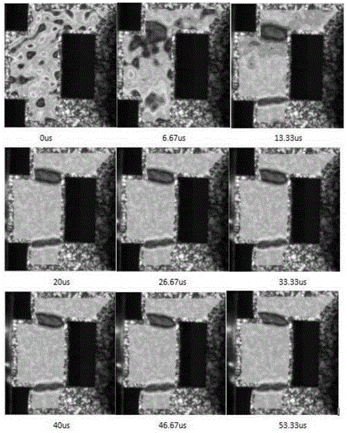
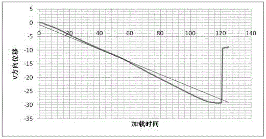
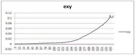
[0039] The invention provides a testing device for the dynamic and static shearing behavior of metals. The core idea is that the prepared convex sample is suitable for both dynamic and static shearing behavior testing, and speckles are made on the surface of the convex sample. , Use digital image correlation method to calculate the collected data to obtain sample deformation strain field related data, which can include deformation strain field cloud image and shear strain rate cloud image, as well as displacement time curve and strain time curve; this method can be directly observed The whole process of sample cutting area and shear deformation, and suitable for dynamic and static shear behavior testing.

[0040] The testing device for metal dynamic and static shearing behavior includes a loading device, a sample, an image acquisition device, and a data processing device...


PUM


Abstract

The invention discloses a testing device for static/dynamic metal shearing behavior. A prepared convex test sample is applicable to dynamic and static shearing behavior testing both, speckle spots can be manufactured on the surface of the convex test sample, acquired data can be calculated by using a digital image relevant method, and then relevant data of a test sample deformation strain field can be obtained. By adopting the method, the operation test sample area shearing and the whole process of shearing deformation can be directly observed. The data calculation process comprises the following steps: by taking a first speckle spot image without deformation as a reference image and other images as deformation images, selecting an area of which the strain is required to be calculated from the reference image, and at the same time selecting a relevant calculation window in the area of which the strain is required to be calculated; determining an appropriate calculation step length according to the resolution of the image, and moving the relevant window to a relatively small strain influence area in the area of which the strain is required to be calculated as a calculating starting point, and starting displacement calculation; after the calculation is completed, selecting points, lines and shearing areas for data analysis according to experiment requirements.

Description

Technical field [0001] The present invention relates to the field of measurement technology, in particular to a testing device for dynamic and static shear behavior of metals. Background technique [0002] In the measurement of metal shearing behavior, not only the dynamic shearing behavior must be measured, but also the static shearing behavior sometimes needs to be measured. In the prior art, the static shearing behavior and the dynamic shearing behavior need to be tested differently. Test device. [0003] The measuring devices used to measure the dynamic shear behavior of metals are as figure 1 As shown, the loading device is composed of a Hopkinson pressure bar, which is divided into an incident bar and a transmission bar, and strain gauges are attached to the incident bar and the transmission bar. The measurement sample is usually a cap type specimen, which is sandwiched between the incident rod and the transmission rod. The bullet hits the incident rod at high speed, and th...

Claims


Application Information

Patent Timeline
IPC IPC(8): G01N3/24
Inventor 陈鹏万张少龙刘海博郭保桥
Owner BEIJING INSTITUTE OF TECHNOLOGYGY
Why Eureka
Try Eureka