Supercharge Your Innovation With Domain-Expert AI Agents!

Optical fiber assembly built in underground cable

A technology of optical fiber components and underground cables, applied in the direction of power cables, electrical components, optical components, etc., can solve problems such as uneven heat of optical fibers, affecting measurement accuracy, and inability to accurately measure the temperature of a predetermined area

Inactive Publication Date: 2015-06-03
STATE GRID CORP OF CHINA +1
View PDF5 Cites 0 Cited by
  • Summary
  • Abstract
  • Description
  • Claims
  • Application Information

AI Technical Summary

Problems solved by technology

In this case, the fiber or catheter may be bent or tilted to one side beyond its design optimum, thus not being able to accurately measure the temperature of the intended area
[0010] The patent application number is 200410035010.5 discloses an optical fiber composite power cable. The optical fiber is placed in a stainless steel pipe. Since the optical fiber is not located on the axis of the stainless steel pipe, the heat transmitted from the cable to the optical fiber is not uniform, which affects the measurement accuracy.

Method used


Image

  • Optical fiber assembly built in underground cable

Examples


Embodiment Construction

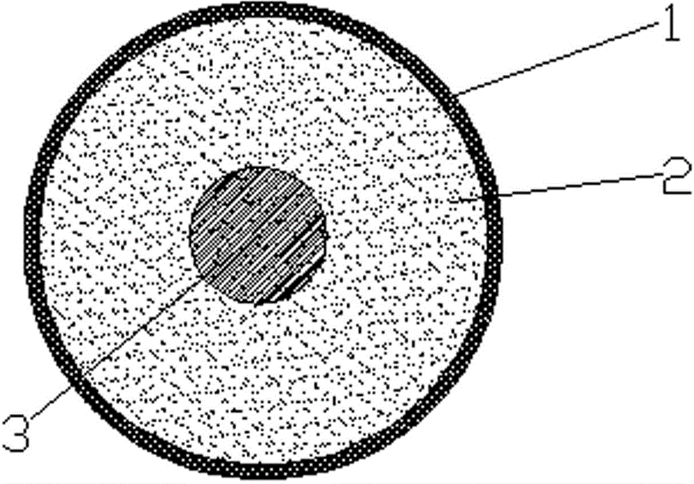
[0016] An optical fiber component placed in an underground cable, including a stainless steel pipe 1 and an optical fiber 3 inside the pipe, the optical fiber 3 is located on the axis of the stainless steel pipe 1, and the space between the optical fiber 3 and the stainless steel pipe 1 is filled with a heat-conducting material 2 that does not affect the optical signal. The heat conducting material 2 is optimally heat conducting glue.

[0017] When the underground power cable is supplied with current, the optical fiber 3 in the optical fiber assembly is located at the axis of the stainless steel pipe 1, supported by heat-conducting adhesive in all directions, and heated evenly, so the measured temperature value is accurate and reliable.


PUM


Abstract

The invention relates to an optical fiber assembly built in an underground cable. The optical fiber assembly comprises a stainless steel pipe and optical fiber in the stainless steel pipe. The stainless steel pipe is filled with heat conduction materials which are heat-conducting glues optimally. The device is simple in structure, the optical fiber is protected, and the temperature condition of the cable can be effectively and accurately measured.

Description

technical field [0001] The invention relates to an underground power cable for transmitting electric power and laid underground, especially an underground power cable with an optical fiber sensor for measuring the distribution temperature of the cable. Background technique [0002] Generally, the temperature of the underground power cable rises when current is applied to the underground power cable, and the ampacity can be calculated based on the highest temperature the underground power cable can withstand. Therefore, when the underground power cable is working, it is very important to measure the temperature of the underground power cable carrying current. However, since it is practically impossible to measure the temperature of a conductor while the underground power cable is carrying current, optical fibers for temperature measurement are usually used. [0003] For example, Korean Patent Publication No. 2003-45864 discloses a system for calculating the temperature of an...

Claims


Application Information

Patent Timeline
Patent Type & Authority Applications(China)
IPC IPC(8): G02B6/44H01B9/00
CPCG02B6/4416H01B9/005
Inventor 乔崇革郝文杰俎洋辉
Owner STATE GRID CORP OF CHINA
Features
  • R&D
  • Intellectual Property
  • Life Sciences
  • Materials
  • Tech Scout
  • Unparalleled Data Quality
  • Higher Quality Content
  • 60% Fewer Hallucinations
Learn More