Flat plate voice coil motor

A voice coil motor, flat panel technology, applied in electrical components, electromechanical devices, electric components, etc., can solve the problems of motor error, increase motor heating, etc.

Active Publication Date: 2015-06-03
SHANGHAI MICRO ELECTRONICS EQUIP (GRP) CO LTD
View PDF4 Cites 23 Cited by
  • Summary
  • Abstract
  • Description
  • Claims
  • Application Information

AI Technical Summary

Problems solved by technology

[0004] Existing planar voice coil motors do not have the gravity compensation function of the mover, so that the operation of the motor will be affected by gravity and cause unnecessary errors. If the gravity compensation function is realized through additional equipment, it is likely to increase the heating of the motor adverse effects of

Method used


Image

  • Flat plate voice coil motor
  • Flat plate voice coil motor
  • Flat plate voice coil motor

Examples


Embodiment 1

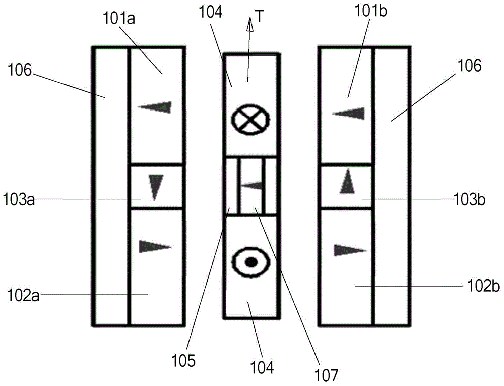
[0038] Please refer to figure 1 , the present embodiment provides a flat panel voice coil motor with a gravity compensation function, including a coil unit and two main pole units, and the two main pole units apply an ampere force T to the coil unit, and the inside of the coil unit It includes a weak magnetic small magnet 107, and the resultant force exerted by the two main magnetic pole units on the weak magnetic small magnet 107 is vertically upward, so as to realize the gravity compensation of the coil unit.

[0039] In this embodiment, a weak magnetic magnet 107 is set in the coil unit, and the magnetic repulsion or magnetic attraction force between the weak magnetic magnet 107 and the main magnetic pole unit always provides a vertical upward force for the coil unit, thereby realizing gravity compensation , and the setting of this structure is only to replace some components in the coil unit with weak magnetic magnets 107, which will neither affect the ampere force receive...

Embodiment 2

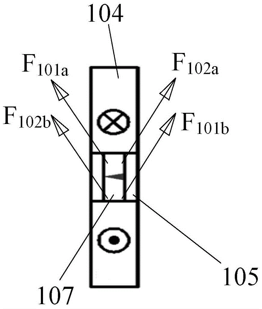
[0051] Please refer to Image 6 with Figure 7 , and combined with Figure 3 to Figure 5 , The difference between this embodiment and Embodiment 1 mainly lies in: the two main magnetic pole units form a vertical main magnetic field, and the two parts of the current-carrying conductors of the coil unit cutting the main magnetic field are arranged left and right. The magnetization direction of the weak magnetic small magnet 107 is the same as the direction of the ampere force applied to the coil unit. The two main pole magnets 101a and 102a located above the coil unit exert a vertical upward magnetic attraction force on the small weak magnet 107; the two main pole magnets 101b and 102b located below the coil unit 102b exerts a vertical upward magnetic repulsion force on the weakly magnetic small magnet 107 . Thus, through the effect of opposite sex attraction between the S pole and the N pole, such as Figure 7 For the diagonally upward F102a and F101a shown, the components ...

Embodiment 3

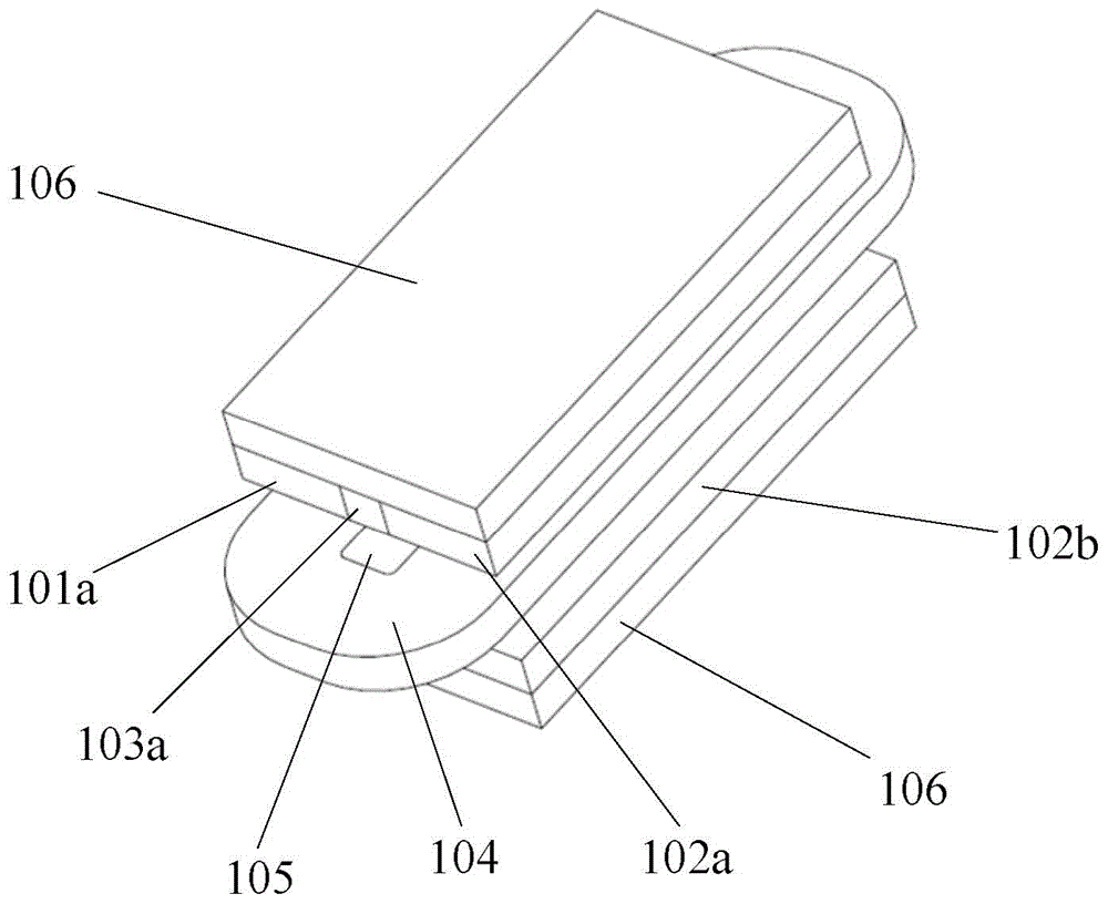
[0055] Please refer to Figure 8 to Figure 11 , the difference between this embodiment and embodiment 1 is only that there is no magnet 103 in this embodiment, and the mechanism of action is consistent with that of embodiment 1. The main magnetic pole unit in this embodiment includes two main magnetic pole magnets and a back iron, the main pole magnet is fixedly arranged on the back iron, and a distance is set between a pair of the main pole magnets; The length of the two weak small magnets along the direction of the two corresponding intervals. Except for this difference, other structures including the main magnetic pole unit, the structure of the coil unit and the arrangement of the components are consistent with those in Embodiment 1.


PUM


Abstract

A flat voice coil motor, comprising a coil unit and two main magnetic pole units. The two main magnetic pole units exert an ampere force on the coil unit. The coil unit comprises a weakly magnetic small magnet (107). The resultant force of the two main magnetic pole units on the weakly magnetic small magnet (107) is vertically upward. The weakly magnetic small magnet (107) is arranged within the coil unit. Via magnetic repulsion or magnetic attraction between the weakly magnetic small magnet (107) and the main magnetic pole units, the coil unit is continually provided with a vertically upward force, thereby compensating for gravity. In the present structure, a portion of the components within the coil unit are replaced with the weakly magnetic small magnet (107). The ampere force received by a coil within the coil unit is not affected, and adverse consequences of increased motor heat generation produced by increasing the structure are avoided.

Description

technical field [0001] The invention relates to semiconductor processing equipment, in particular to a flat voice coil motor. Background technique [0002] The flat-plate voice coil motor manufactured based on the principle of ampere force has the advantages of simple structure, convenient maintenance, high reliability, high energy conversion efficiency, fixed stroke and direct drive characteristics, smooth force stroke output and linear control, and electrical and mechanical time Low constant, high thrust / mass ratio, no cogging, no need for commutation, theoretically infinite position sensitivity, no cogs, no hysteresis response, so that voice coil motors can be well applied in applications requiring high speed and high acceleration , Linear force or torque response servo control, based on the above characteristics, the voice coil motor is very suitable for the precision positioning unit of the lithography machine that requires fast and high-precision positioning. [0003]...

Claims


Application Information

Patent Timeline
Patent Type & Authority Applications(China)
IPC IPC(8): H02K33/18
CPCH02K7/09H02K41/0356H02K1/17H02K1/34
Inventor 段素丙张志钢陈庆生刘小虎
Owner SHANGHAI MICRO ELECTRONICS EQUIP (GRP) CO LTD
Why Eureka
Try Eureka