Eureka AIR delivers breakthrough ideas for toughest innovation challenges, trusted by R&D personnel around the world.

A method for matching refrigeration load to compressor capacity

A compressor and cooling capacity technology, which is applied in the direction of refrigerators, compressors, compressors with multiple condensers, etc., can solve problems such as compressor wear and tear, and achieve an easy-to-achieve effect

Active Publication Date: 2015-06-03
DANFOSS AS
View PDF5 Cites 6 Cited by
  • Summary
  • Abstract
  • Description
  • Claims
  • Application Information

AI Technical Summary

Problems solved by technology

However, repeatedly switching a compressor on and off can cause wear and tear on the compressor

Method used


Image

  • A method for matching refrigeration load to compressor capacity
  • A method for matching refrigeration load to compressor capacity
  • A method for matching refrigeration load to compressor capacity

Examples


Embodiment Construction

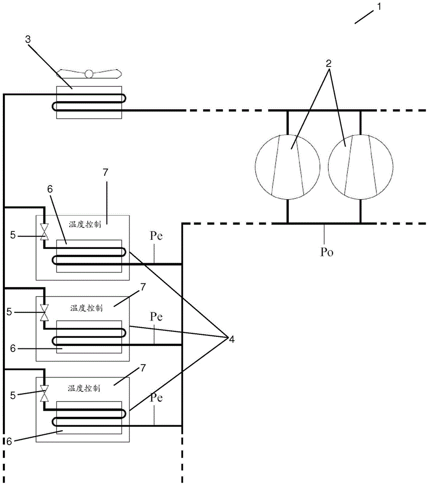
[0061] figure 1 is a diagrammatic view of a refrigeration system 1 controlled by a method according to an embodiment of the invention. The refrigeration system 1 comprises a plurality of compressors 2, two of which have been shown. The compressors 2 are arranged in a compressor train. The refrigeration system 1 further comprises a condenser 3 and a plurality of refrigeration entities 4, three of which have been shown.

[0062] Each refrigeration entity includes an expansion device 5 , an evaporator 6 and an entity controller 7 . The entity controller 7 controls the corresponding cooling entity 4 , including supplying refrigerant to the evaporator 6 .

[0063] The refrigeration system 1 can operate in the following manner. The refrigerant is compressed in the compressor 2 , then passed into a condenser, where the refrigerant is condensed and heat is removed from the refrigerant, and further passed towards the refrigeration entity 4 . In the refrigeration entity, this refri...


PUM


Abstract

A method for controlling operation of a refrigeration system (1), comprising one or more refrigeration entities (4), is disclosed. Each entity controller (7) obtains a measure for an error value between the measured value of a compressor control parameter and a setpoint value (8) for the compressor control parameter, and each entity controller (7) adjusts a refrigeration load of the corresponding refrigeration entity (4) to correspond to a cooling capacity of the compressor(s) (2), and in accordance with the obtained measure for an error value.

Description

technical field [0001] The invention relates to a method for controlling the operation of a refrigeration system in such a way that switching on and off of a compressor is minimized. Background technique [0002] A refrigeration system typically includes one or more compressors, one or more condensers, and one or more refrigeration entities arranged in a refrigeration path. Each refrigeration entity comprises one or more evaporators and an expansion device arranged to provide a flow of refrigerant to the one or more evaporators. The one or more evaporators provide refrigeration to a refrigerated volume, and the temperature within the refrigerated volume can be controlled by allowing or preventing a flow of refrigerant through the one or more evaporators. [0003] These refrigeration entities may for example be cooling and / or freezers of the kind applied eg in supermarkets. [0004] In such refrigeration systems, the cooling capacity provided by the one or more compressors ...

Claims


Application Information

Patent Timeline
IPC IPC(8): F25B5/02F25B6/00F25B49/02
CPCF25B5/02F25B6/00F25B49/022F25B2600/2513F25B2600/0251F25B2400/075F25B2600/0272F25B2600/0253F25B2700/21172Y02B30/70F25B7/00F25B49/02F25D2600/06
Inventor 简·普瑞斯佛瑞德·施密特托苯·格林
Owner DANFOSS AS
Why Eureka
Eureka Blog
Learn More