Device for producing direct current passing into load power-supply circuits

A technology of DC voltage, DC voltage source, applied in the direction of regulating electrical variables, control/regulating systems, instruments, etc., can solve problems such as lack of power, low power dissipation, etc.

Active Publication Date: 2015-06-03
CLOSED UP JOINT STOCK COMPANY DRIVE
View PDF8 Cites 4 Cited by
  • Summary
  • Abstract
  • Description
  • Claims
  • Application Information

AI Technical Summary

Problems solved by technology

[0006] The technical result that the above prior art fails to achieve is stabilization at the DC stabilizer resulting in lower power dissipation and voltage drop at the DC stabilizer when the load impedance changes
[0007] The reason for not realizing the ab

Method used


Image

  • Device for producing direct current passing into load power-supply circuits
  • Device for producing direct current passing into load power-supply circuits

Examples


Embodiment Construction

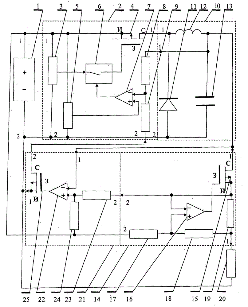
[0015] Devices for supplying constant current to loads include:

[0016] - a DC voltage source 1, comprising, for example, a band filter of (a) full-wave rectifier;

[0017] - (a) DC-to-pulse voltage converter 2 comprising: first and second terminals connected (at) via its terminals (first and second input terminals of its direct-to-pulse voltage converter 2 ) to a DC voltage source Square pulse generator 3 of constant frequency; (Square pulse generator 3 of constant frequency;) Controllable gate circuit 6 is connected to constant frequency square wave pulse generator 3 and its output port-to MOP - gate of transistor 4; OA7 connects its output to a control input of said controllable gate circuit 6 and via its non-inverting terminal ("+") input - to the output of a reference voltage source 5; (the) first resistor 8, the first terminal of which is connected to the inverting ("-") input of an OA7 and the (one) second terminal is connected to the first control of a DC-to-pulse vo...


PUM


Abstract

The invention relates to a device for producing direct current passing into load power-supply circuits. The invention relates to the field of electrical engineering. The device comprises a DC voltage source, a DC voltage-to-pulsed voltage converter, a pulsed voltage-to-DC voltage converter, and a DC stabilizer. A first input of the DC stabilizer is connected to an output of the pulsed voltage-to-DC voltage converter, a second input of the DC stabilizer is connected to a positive output of the DC voltage source, and a first output of the DC stabilizer is connected to one of the load terminals. The other terminal of said load is connected to a negative output of the DC voltage source. The device also comprises a control circuit, wherein a first input of the control circuit is connected to the output of the pulsed voltage-to-DC voltage converter, a second input of the control circuit is connected to a second output of the DC stabilizer, a first output of the control circuit is connected to a second output of the DC voltage source, and a second output of the control circuit is connected to a second control input of the pulsed voltage-to-DC voltage converter. The result is the stabilization of dissipation power in the stabilizer.

Description

technical field [0001] The present invention relates to electrical engineering and makes power supplies more efficient. Background technique [0002] Well known in the art is the LED light source (RU93611U1, published on April 27, 2010), which includes the following functions: AC / DC voltage converter; capacitor filter connection and termination to the output of the AC / DC voltage converter terminal; the DC / DC lower voltage converter is connected with its input to the capacitor filter terminal; the DC stabilizer (comprised of a) voltage stabilizer and (one) resistor connected to the output of the voltage stabilizer through its terminals; and by the load termination resistor The other terminal of the load-to-negative terminal of the AC / DC voltage converter is connected (by the other) load terminal. [0003] Common features of the present invention and the prior art are: (a) DC voltage source, DC stabilizer, (and) one of the outputs to the DC stabilizer via the load terminal, (...

Claims


Application Information

Patent Timeline
IPC IPC(8): G05F1/563
Inventor Y·I·罗曼诺夫
Owner CLOSED UP JOINT STOCK COMPANY DRIVE
Why Eureka
Try Eureka