
A light oil tank circulation slag flushing device and slag flushing cleaning method

A technology for light oil and slag flushing, applied in cleaning methods and utensils, separation methods, chemical instruments and methods, etc., can solve the problems of difficult environmental protection work, spontaneous combustion of ferrous sulfide, and high danger, saving resources, The effect of avoiding waste and convenient operation

Active Publication Date: 2017-06-23
山东莱钢环友化工能源有限公司
View PDF6 Cites 0 Cited by
  • Summary
  • Abstract
  • Description
  • Claims
  • Application Information

AI Technical Summary

Problems solved by technology

[0005] The current existing storage tank cleaning technology needs to open the storage tank manhole, use high-pressure water for flushing, and require personnel to enter the storage tank for operation, which is dangerous and produces a large amount of industrial sewage, making environmental protection work difficult.
In addition, due to the high content of sulfur ions in the raw material crude benzene, ferrous sulfide is formed on the inner wall of the storage tank. Once the manhole of the storage tank is opened and a large amount of air enters, it is easy to cause the ferrous sulfide to spontaneously ignite, and then ignite the benzene vapor and air inside the storage tank. Mixed gas with risk of fire and explosion

Method used


Image

  • A light oil tank circulation slag flushing device and slag flushing cleaning method

Examples


Embodiment 1

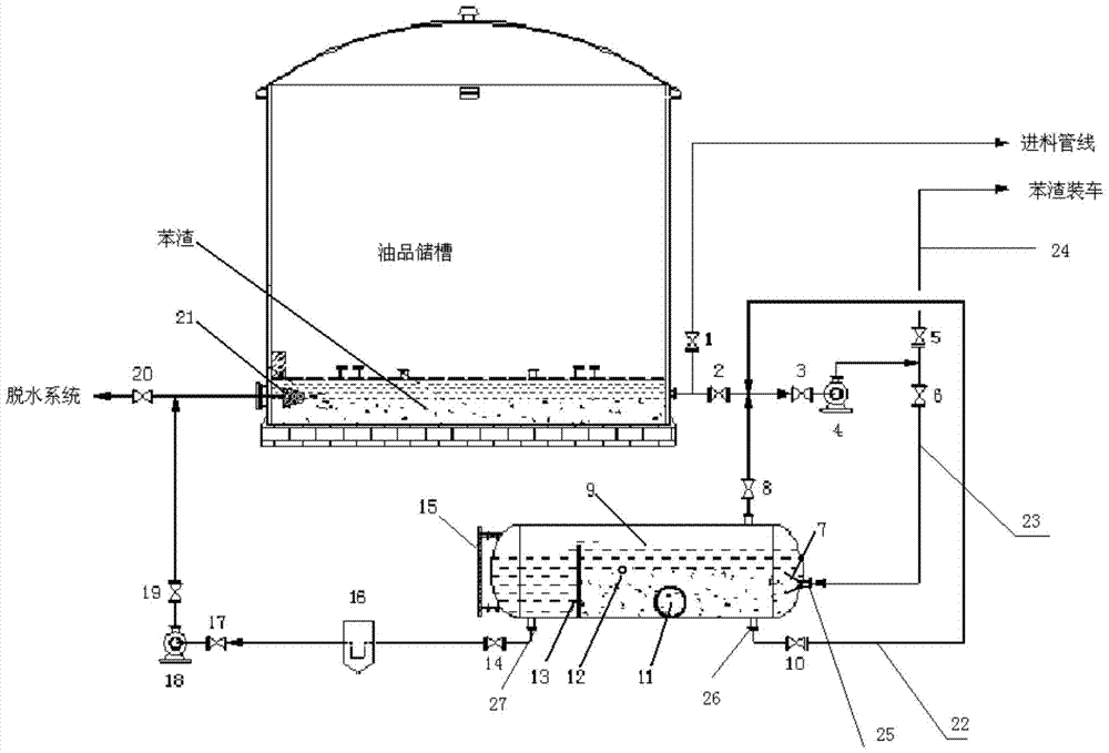
[0037] A light oil tank circulation slag flushing device, the structure is as follows figure 1 As shown, there is a circulating slag flushing branch externally connected to the feed pipeline of the light oil tank, and the circulating slag flushing branch includes a first circulating slag flushing pump 4, a benzene slag sedimentation tank 9 and a second circulating slag flushing pump connected in series through pipelines. The slag pump 18, the inlet of the first circulating slag washing pump 4 is connected with the feed pipeline of the light oil tank, and the outlet of the first circulating slag washing pump 4 is connected with an external benzene slag sending pipeline 24 and a circulating slag washing inlet pipe 23 through pipelines, Circulation flushing slag inlet pipe 23 is connected with feed port 25 of benzene slag sedimentation tank, benzene slag sedimentation tank outlet 27 is connected with the inlet of second circulation slag flushing pump 18, and the outlet of second c...

Embodiment 2

[0041] A light oil tank circulating slag flushing device, the structure is the same as that described in Embodiment 1, the difference is:

[0042] The top of the benzene slag sedimentation tank is provided with a full flow port connected to the inside of the benzene slag sedimentation tank. The full flow port is connected with a full flow pipeline, and the pipe between the full flow pipeline and the first circulation slag washing pump and the light oil tank feed line The flow path is connected, and the full-flow material enters the circulating slag flushing branch through the full-flow pipeline, and a full-flow control valve 8 is set on the full-flow pipeline.

Embodiment 3

[0044] A light oil tank circulating slag flushing device, the structure is the same as that described in Embodiment 1, the difference is:

[0045] There is also a nitrogen purge pipeline connected to the pipeline between the outgoing benzene slag pipeline 24 and the connection between the circulating slag flushing branch and the first circulating slag flushing pump.


PUM

PropertyMeasurementUnit
bearing capacityaaaaaaaaaa

Abstract

The invention relates to a light oil tank circulating slag flushing device. A circulating slag flushing branch circuit is externally connected to a light oil tank feeding pipeline, and comprises a first circulating slag flushing pump, a benzene slag sedimentation tank and a second circulating slag flushing pump, wherein the first circulating slag flushing pump, the benzene slag sedimentation tank and the second circulating slag flushing pump are connected together in series through pipelines; an inlet of the first circulating slag flushing pump is communicated with the light oil tank feeding pipeline, and the benzene slag sedimentation tank is a horizontal sealed tank; a slag baffle is longitudinally arranged inside the benzene slag sedimentation tank, and the area in the benzene slag sedimentation tank is divided by the slag baffle into a benzene slag sedimentation area and a clear oil product area; a benzene outlet is connected with a benzene slag pipeline, and the benzene slag pipeline is communicated with a pipeline located between the first circulating slag flushing pump and the light oil tank feeding pipeline. The light oil tank circulating slag flushing device is simple in structure and convenient to improve, install and operate; storage tank circulating slag flushing cleaning is conducted regularly, accumulation of benzene slag in a storage tank is reduced, the continuous service cycle of the storage tank is prolonged, and stable operation of a follow-up processing system is guaranteed.

Description

technical field [0001] The invention relates to a light oil tank circulation slag washing device and a slag cleaning method, belonging to the technical field of light oil tank technology. Background technique [0002] With the continuous development of benzene hydrogenation technology and the continuous expansion of the scale of the benzene hydrogenation industry, the competition for crude benzene resources, one of the main raw materials of benzene hydrogenation enterprises, is intensifying, resulting in the quality requirements of raw materials for crude benzene in benzene hydrogenation enterprises The content of harmful ions such as sulfur and chlorine and heavy components such as heavy benzene and naphthalene in the raw material crude benzene continues to increase. In addition, affected by the equipment materials and storage conditions of the raw material crude benzene production enterprises, the raw material crude benzene contains some benzene slag formed by rust, aromat...

Claims


Application Information

Patent Timeline
Patent Type & Authority Patents(China)
IPC IPC(8): B08B9/28B01D21/02B01D36/04
CPCB01D21/02B01D36/04B08B9/28
Inventor 王欢罗玉辉蒋淑艳李健林金良秦立琴许坤李国军国徽
Owner 山东莱钢环友化工能源有限公司
Learn More