Decomposing furnace based on multi-fuel injection technology
A calciner and multi-fuel technology, applied in clinker production, cement production, etc., can solve the problems that affect the overall burnout rate of coal powder, high volatile content, and hinder the full combustion of coal powder, so as to improve the burnout rate, The effect of high burnout rate and high decomposition rate of raw meal
- Summary
- Abstract
- Description
- Claims
- Application Information
AI Technical Summary
Problems solved by technology
Method used
Image

Examples
Example Embodiment
[0028] Example 1: A cement clinker decomposition furnace with a daily output of 2000 tons
[0029] (1) Set the main fuel as high-quality coal and the secondary fuel as low-quality coal.
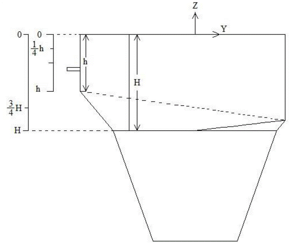
[0030] (2) The height position of the main fuel pulverized coal injection point A=h / 2;
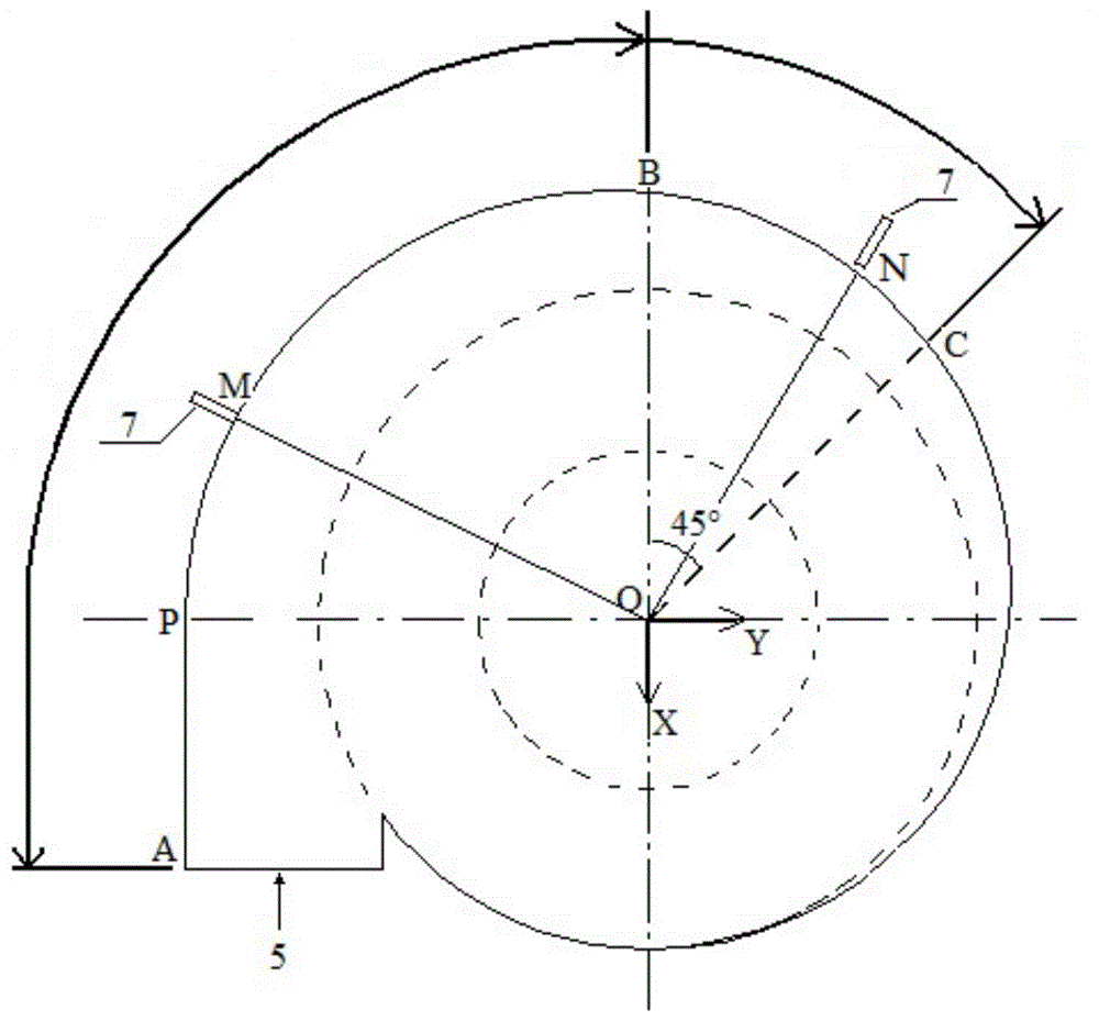
[0031] (3) Only one main fuel nozzle 7 is provided, and its plane position is at point M in section AB, where the MOB angle is 20°;
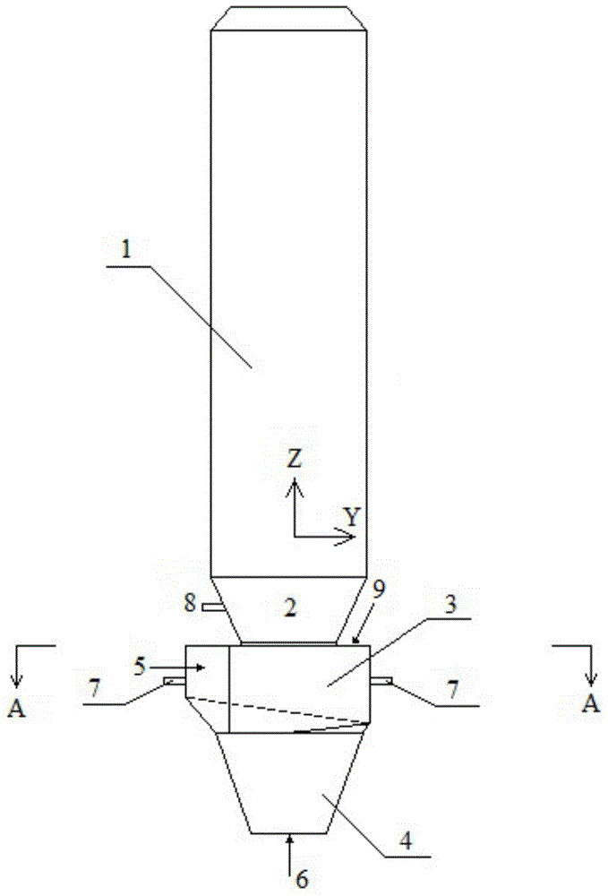
[0032] (4) Set the secondary fuel nozzle 8 on the top surface of the swirl pre-combustion chamber 3;
[0033] (5) At this time, the model predicts that the overall fuel burn rate is 88%, and the calcium carbonate decomposition rate is 91%.
[0034] (6) When only the main fuel is injected, the comparison of the indicators in the two pulverized coal entry modes from the top of the swirl pre-combustion chamber 3 and side coal injection is shown in Table 1.
[0035] Table 1 Index comparison of 2000 tons of cement clinker calciner per day under two injection methods
[0036]
Example Embodiment
[0037] Example 2: A cement clinker decomposition furnace with a daily output of 5000 tons
[0038] (1) Set the main fuel as pulverized coal and the secondary fuel as RDF;
[0039] (2) The height position of the injection point of the main fuel high-quality pulverized coal A=2h / 3;
[0040] (3) Two main fuel nozzles 7 are provided. One of the main fuel nozzles 7 is located at point M in section AB, and the MOB angle is 75°; the other main fuel nozzle 7 is located at section BC. At point N in the middle, the angle of NOB is 15°;
[0041] (4) Install the secondary fuel nozzle 8 in the cone part 2 of the spray furnace 1;
[0042] (5) The model predicts that the burning rate of pulverized coal is 93%, and the decomposition rate of calcium carbonate is 95%.
[0043] (6) When only the main fuel is injected, the main fuel coal is injected from the top of the swirl pre-combustion chamber 3 and the main fuel coal is injected from the side. The comparison of each index is shown in Table 2.
[0044] ...
Example Embodiment
[0046] Example 3: Cement clinker decomposition furnace with a daily output of 10,000 tons
[0047] (1) Set the main fuel as pulverized coal and the secondary fuel as petroleum coke.
[0048] (2) The height position of the pulverized coal injection point A=2H / 3;
[0049] (3) Two main fuel nozzles 7 are provided, of which the plane position of one main fuel nozzle 7 is located at point A in section AB; the plane position of the other main fuel nozzle 7 is located at point C in section BC;
[0050] (4) Set the secondary fuel in the column part of the spray furnace 1;
[0051] (5) The model predicts that the burning rate of pulverized coal is 100%, and the decomposition rate of calcium carbonate is 100%.
[0052] (6) When only the main fuel is injected, the comparison of the indicators is shown in Table 3 in the two pulverized coal entry modes from the top of the swirl pre-combustion chamber 3, coal injection and side coal injection.
[0053] Table 3 Comparison of indicators of 10,000 tons of...
PUM
 Abstract
Description
Claims
Application Information
 - R&D Engineer
- R&D Manager
- IP Professional
- Industry Leading Data Capabilities
- Powerful AI technology
- Patent DNA Extraction
Browse by: Latest US Patents, China's latest patents, Technical Efficacy Thesaurus, Application Domain, Technology Topic.
© 2024 PatSnap. All rights reserved.Legal|Privacy policy|Modern Slavery Act Transparency Statement|Sitemap