Bearing seat
A bearing seat and bearing cavity technology, applied in the direction of bearing components, shafts and bearings, rigid brackets of bearing components, etc., can solve the problems of difficult positioning, high speed of the shredding device, unreliable performance, etc. Reasonable and reliable, conducive to the effect of lubrication
- Summary
- Abstract
- Description
- Claims
- Application Information
AI Technical Summary
Problems solved by technology
Method used
Image
Examples
Embodiment Construction
[0019] Below in conjunction with accompanying drawing, the present invention will be further described:
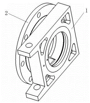
[0020] The bearing seat can be seen from Figure 1, which is composed of the bearing seat body 2 and the seat body square sleeve 1.
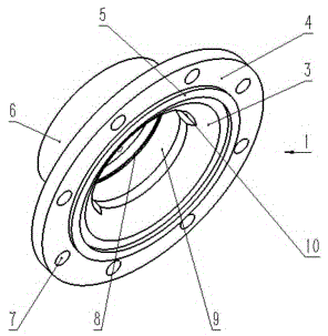
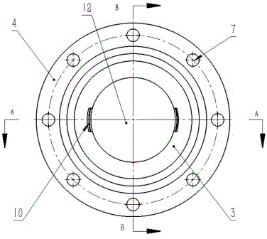
[0021] Depend on Figure 2 to Figure 5 It can be seen that one end of the bearing body is a flange 4, and positioning holes 7 are evenly distributed on the flange. The cavity surrounded by the shaped boss is the bearing cavity 12, and the shape in the cylindrical boss is the spherical shape cavity 9 that cooperates with the outer spherical bearing; a circle of positioning seams is set between the flange and the large arc opening 5. There are two symmetrical installation grooves 10 on the spherical shape cavity in the bearing cavity, and an oil groove 8 is opened on the above spherical shape cavity, and the oil hole 11 connected to the oil groove is set in the port of the cylindrical boss 6 .
[0022] Such as figure 1 , Figure 6 , Figu...
PUM
 Abstract
Description
Claims
Application Information
 - R&D
- Intellectual Property
- Life Sciences
- Materials
- Tech Scout
- Unparalleled Data Quality
- Higher Quality Content
- 60% Fewer Hallucinations
Browse by: Latest US Patents, China's latest patents, Technical Efficacy Thesaurus, Application Domain, Technology Topic, Popular Technical Reports.
© 2025 PatSnap. All rights reserved.Legal|Privacy policy|Modern Slavery Act Transparency Statement|Sitemap|About US| Contact US: help@patsnap.com


