
Electomotor

A technology of electric motors and pole shoes, applied in the field of electric motors, can solve the problems of low torque density, high cost, and expensive motors, etc., and achieve the effect of compact structure and low cost

Active Publication Date: 2015-06-10
ROBERT BOSCH GMBH
View PDF4 Cites 7 Cited by
  • Summary
  • Abstract
  • Description
  • Claims
  • Application Information

AI Technical Summary

Problems solved by technology

[0003] The disadvantage of this prior art is that such electric motors have only a relatively low torque density due to the rare earth-free permanent magnets and thus cannot be used in applications that require a relatively high torque density in one or more possible operating states. in application
Although an increase in the torque density can be achieved here by using rare-earth permanent magnets, this is relatively costly and thus makes the motor more expensive

Method used


Image

  • Electomotor
  • Electomotor
  • Electomotor

Examples


Embodiment approach

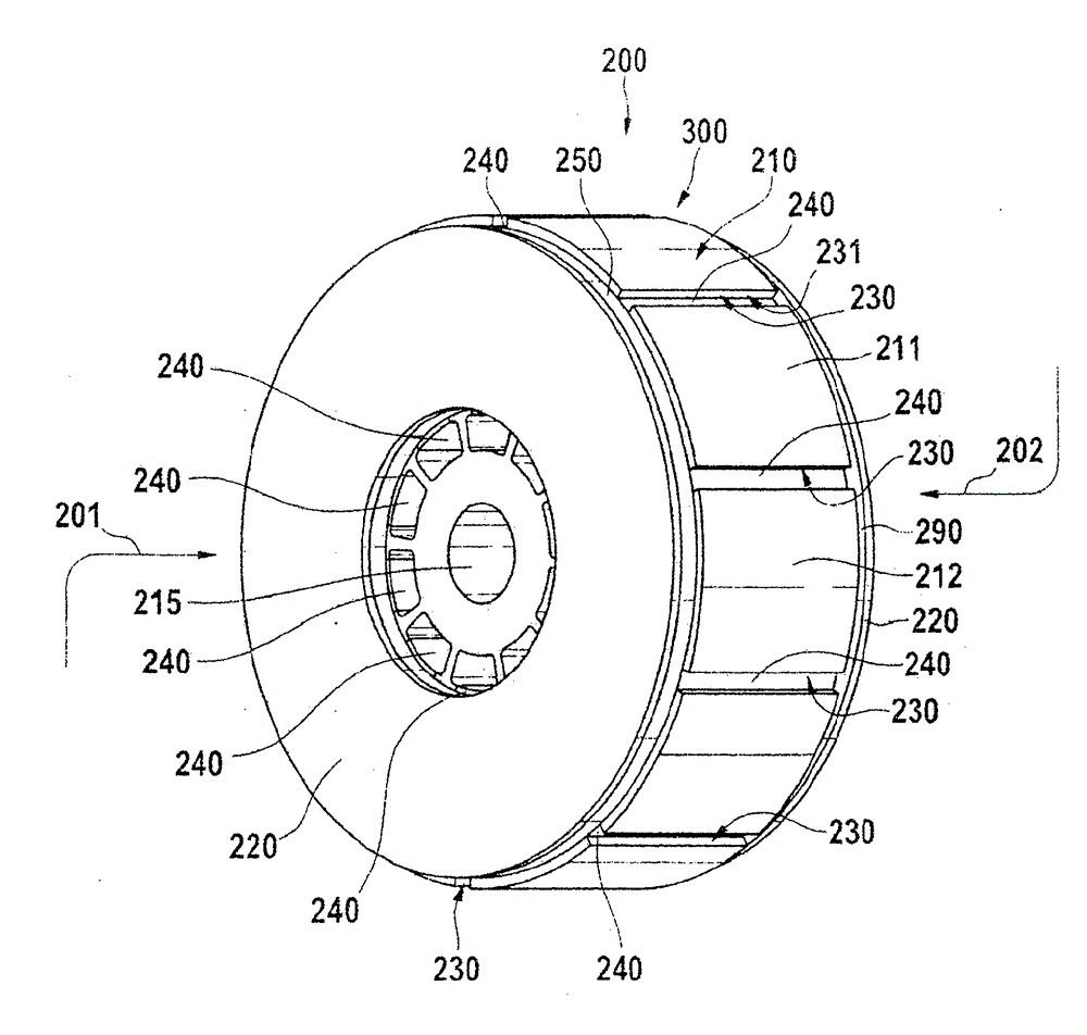
[0040] According to one specific embodiment, the rotor core 300 has a plurality 210 of pole shoes 211 , 212 which preferably form a plurality 231 of recesses 230 oriented at least approximately in the manner of spokes for accommodating a plurality of permanent magnets 240 . However, it should be pointed out that the plurality 231 of recesses 230 is arranged here in a spoke-like manner only for illustration and not as a limitation of the invention, and can alternatively be formed on rotor core 300 in any other manner. The permanent magnet 240 is preferably glued and / or clamped or pressed into the recess 230 . Depending on the type of bulk magnet, permanent magnet 240 preferably consists of a rare earth-free material, but can alternatively also comprise rare earth material.

[0041] According to one specific embodiment, at least one preferably disk-shaped or plate-shaped multipole magnet 250 , 290 , which is referred to below as a “disk magnet” for simplicity of description, is ...

no. 1 approach

[0045] explanatory in image 3 A disk magnet 250 , 290 is respectively arranged on each end side 201 , 202 of rotor core 300 . According to a first embodiment, each of the disk magnets 250 , 290 has a disk-shaped base body 399 , 398 with a plurality 342 of disk segments 340 , 341 , wherein the plurality of disk segments 340 , 341 Each disk segment in is made up of one permanent magnet in a plurality 322 of permanent magnets 320,321. The plurality 322 of permanent magnets 320 , 321 preferably has an even number of permanent magnets 320 , 321 which corresponds to the predetermined number of pole shoes 211 , 212 of rotor core 300 or the number of permanent magnets 240 .

[0046] By way of explanation, permanent magnet 320 for forming disk segment 340 has a magnetic north pole on its end face facing away from rotor core 300 , and permanent magnet 321 for forming disk segment 341 has a magnetic south pole. Overall, the plurality 322 of permanent magnets 320 , 321 form the disk ma...


PUM


Abstract

The invention relates to an electromotor having a stator and a rotor (200). The rotor (200) is provided with a rotor core (300) having a plurality of pole shoes (210, 211, 212). The pole shoe is provided with a plurality of recess parts (230) for accommodating permanent magnets (240) in the pole shoe (300). The permanent magnet is structured for producing a magnetic pole corresponding to the rotor (200) in each pole shoe (211, 212). At least one end side (201, 202) of the rotor core (300) is provided with at least one axially-magnetized permanent magnet in at least one pole shoe area for strengthening the magnetic pole (260) produced by at least one pole shoe (211, 212).

Description

technical field [0001] The invention relates to an electric motor with a stator and a rotor, wherein the rotor has a rotor core with a plurality of pole shoes, the pole shoes forming a plurality of recesses for receiving permanent magnets in the rotor core, the recesses being formed with The purpose is to form the corresponding magnetic poles of the rotor in the respective associated pole shoes. Background technique [0002] Such electric motors are known from the prior art with a rotor core whose rotor core has a plurality of recesses oriented at least approximately in the form of spokes for receiving permanent magnets. For reasons of cost, the permanent magnets are produced from a rare-earth-free material and each generate a tangentially oriented main flux in order to form magnetic poles in associated pole shoes of the rotor core. [0003] The disadvantage of this prior art is that such electric motors have only a relatively low torque density due to the rare earth-free p...

Claims


Application Information

Patent Timeline
IPC IPC(8): H02K1/27
CPCH02K1/2706H02K1/2713H02K1/2766
Inventor S. A. 埃文斯
Owner ROBERT BOSCH GMBH
Learn More