Inlet guide vane assembly

An air intake guide vane assembly and blade technology, which is applied to pump components, engine components, components of a pumping device for elastic fluids, etc., can solve the problems of difficult manufacturing, air tightness and appearance of external actuators, etc. Poor, complex structure, etc.

Active Publication Date: 2015-06-17
IND TECH RES INST
View PDF7 Cites 24 Cited by
  • Summary
  • Abstract
  • Description
  • Claims
  • Application Information

AI Technical Summary

Problems solved by technology

[0004] In order to overcome the above-mentioned defects in the prior art, the object of the present invention is to provide an air intake guide vane assembly, which can provide precise fluid flow control, and

Method used


Image

  • Inlet guide vane assembly
  • Inlet guide vane assembly
  • Inlet guide vane assembly

Examples


Embodiment Construction

[0051] The technical means and effects used by the present invention to achieve the purpose will be described below with reference to the accompanying drawings, and the embodiments listed in the following drawings are only for auxiliary illustration, but the technical means of this case are not limited to the listed accompanying drawings .

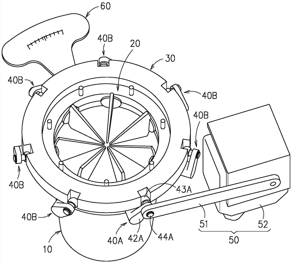
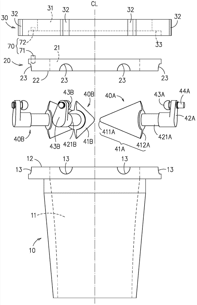
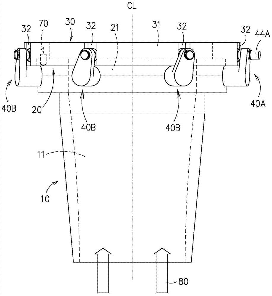
[0052] see Figure 1 to Figure 5 An embodiment of the air inlet guide vane assembly provided by the present invention is shown, which includes a housing 10, a fixed ring 20, a rotating ring 30, a plurality of vane devices 40A, 40B and a driving member 50; in addition, as figure 1 As shown, the present embodiment further includes a scale indicator 60, the scale indicator 60 is connected to the rotating ring 30, the setting of the scale indicator 60 depends on actual needs, and may not be provided, and the type of the scale indicator 60 and Any form figure 1 shown.

[0053] The outer shape of the housing 10 is a hollow cylindrical structu...


PUM


Abstract

An inlet guide vane assembly is disclosed, which comprises: a housing, configured with a first penetration part and a plurality of first grooves; at least one fixing ring, each configured with a second penetration part and a plurality of second grooves; at least one rotary ring, each configured with a third penetration part and a plurality of sliding chutes, wherein the first, the second and the third penetration parts are arranged in communication with one another; a plurality of vane units, each vane unit is composed of a vane, a linkage and a sliding block; and at least one driving unit, for driving one vane of the plural vanes to swing, thus driving the rotary ring to rotate simultaneously, bringing along the other vanes to swing, enabling the sliding blocks to slide inside corresponding sliding chutes, and consequently flipping the vane from a first state to a second state.

Description

technical field [0001] The invention relates to an air intake guide vane assembly, in particular to an air intake guide vane assembly which simplifies the structure, reduces the difficulty of assembly, reduces the cost and solves the problem of external placement of the actuator. Background technique [0002] The technology of using blade angle to control fluid flow is used in different technical fields. For air-conditioning applications, when the centrifugal compressor operates under different loads, different flow paths must be formed before the impeller inlet by opening and closing the guide vanes. area to adjust equipment load by controlling fluid flow. Therefore, if the intake guide vane at the compressor inlet cannot be accurately controlled, the load of the chiller cannot be controlled, which will inevitably result in serious energy waste. [0003] However, most of the existing air inlet guide vanes are mechanisms that use connecting rods and gears, or drive the toot...

Claims


Application Information

Patent Timeline
IPC IPC(8): F04D29/46
CPCF01D9/04F01D17/14F01D17/141F01D17/145F01D17/146F01D17/148F01D17/16F01D17/162F01D17/165F01D17/167F04D29/462
Inventor 洪国书钟震麒刘中哲
Owner IND TECH RES INST
Why Eureka
Try Eureka