High-speed cylinder with buffer device

A high-speed, cylinder technology, applied in the direction of fluid pressure actuating devices, etc., can solve the problems of piston assembly and cylinder end cover deformation, ordinary cylinder can not meet, short cylinder stroke, etc., to achieve the effect of increasing the pressure difference

Active Publication Date: 2015-06-17
AEROSPACE LIFE SUPPORT IND LTD
View PDF10 Cites 2 Cited by
  • Summary
  • Abstract
  • Description
  • Claims
  • Application Information

AI Technical Summary

Problems solved by technology

[0003] At present, in the production process, it is necessary to provide a high-speed cylinder with a speed greater than 3m/s. For example, according to the requirements of civil aviation passenger seats for the HIC value test of the dummy in the test, a high-speed cylinder is required to make a dummy head module weighing about 6kg. Accelerate to a speed of no less than 10.4m/s within a certain stroke. At the same time, due to the limitation of th

Method used


Image

  • High-speed cylinder with buffer device
  • High-speed cylinder with buffer device
  • High-speed cylinder with buffer device

Examples


Embodiment Construction

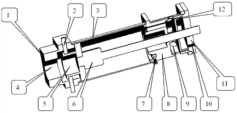
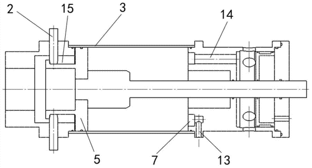
[0027] Such as figure 1 , 2 As shown, the embodiment of the high-speed cylinder with buffer device of the present invention includes a cylinder block 3, a piston assembly 5, a piston rod 6, a rear end cover 1 and a front end cover 11; the rear end cover and the front end cover are respectively arranged on the rear of the cylinder block There is an air inlet 4 on the rear end cover, which communicates with the pressure air source, and a hole on the front end cover; the piston assembly is arranged in the cylinder, one end of the piston rod is connected to the piston assembly, and the other end Passing through the hole on the front end cover, the piston rod 6 and the front end cover 11 are sealed with a common rubber sealing ring; the cylinder is also provided with a buffer piston 8 which is arranged between the piston assembly and the front end cover to buffer The piston is provided with a hole for the piston rod to pass through; the cylinder is provided with an exhaust port 9, wh...


PUM


Abstract

The invention relates to a high-speed cylinder with a buffer device. The high-speed cylinder with the buffer device comprises a cylinder body, a piston component, a piston rod, a rear end cover and a front end cover. The rear end cover and the front end cover are arranged at the rear end and the front end of the cylinder body respectively, the rear end cover is provided with an air inlet, and the front end cover is provided with a hole. The piston component is arranged in the cylinder body, one end of the piston rod is connected with the piston component, and the other end of the piston rod penetrates out of the hole in the front end cover. A buffer piston is further arranged in the cylinder body and located between the piston component and the front end cover, and the buffer piston is provided with a hole for the piston rod to penetrate through. Exhaust outlets are formed in the cylinder body and located between the buffer piston and the front end cover. A vent hole enabling the front side and the rear side of the buffer piston to be communicated is formed in the buffer piston. The cylinder is provided with the buffer device, and the piston component of the cylinder can be effectively prevented from directly impacting the cylinder end covers.

Description

Technical field [0001] The invention relates to a cylinder, especially a high-speed cylinder with a speed greater than 3m / s. Background technique [0002] Ordinary cylinders generally consist of front and rear end covers, cylinder walls, pistons and piston rod assemblies. The thrust generated by the pressure difference between the two sides of the cylinder piston drives the movement of the piston rod, which in turn drives the movement of the objects in contact with the piston rod. The thrust of the cylinder is equal to the product of the pressure difference between the two sides of the piston and the cross-sectional area of ​​the piston. The movement speed of the cylinder and the thrust of the cylinder are summed The stroke of the cylinder is proportional. Due to the large impact of the piston, the maximum speed of the general cylinder can only be 3m / s. [0003] At present, in the production process, it is necessary to provide a high-speed cylinder with a speed greater than 3m / s. ...

Claims


Application Information

Patent Timeline
IPC IPC(8): F15B15/20F15B15/22
CPCF15B15/1428F15B15/224F15B15/227F15B15/261
Inventor 谢武俊闵立武沈文波
Owner AEROSPACE LIFE SUPPORT IND LTD
Why Eureka
Try Eureka