
Automatic overrun clutch

An overrunning clutch and clutch technology, applied in the field of clutches, can solve the problems of troublesome use and the inability of the inner sleeve of the small wheel to rotate along with it, and achieve the effect of simple structure

Inactive Publication Date: 2015-06-17
李明阳
View PDF8 Cites 6 Cited by
  • Summary
  • Abstract
  • Description
  • Claims
  • Application Information

AI Technical Summary

Problems solved by technology

[0002] The currently used overrunning clutch is a one-way overrunning clutch, which includes a small wheel inner sleeve with a limit groove. The small wheel inner sleeve is covered with a small wheel outer sleeve. The ratchet of the small wheel has a spring hole on the inner sleeve of the small wheel. The spring steel wire of the small wheel is inserted in the spring hole. The free end of the ratchet of the small wheel is in contact with the end of the spring steel wire of the small wheel. The free end of the ratchet of the small wheel The end is located outside the spring steel wire of the small wheel. The inner surface of the small wheel jacket is designed with small wheel teeth. When using this structure, the inner sleeve of the small wheel actively rotates forward, and the ratchet teeth of the small wheel are embedded in the teeth of the small wheel to lock, driving the outer cover of the small wheel to rotate forward. The teeth of the small wheel in the wheel outer cover are pushed out and cannot be locked, and the inner wheel of the small wheel cannot rotate accordingly, that is to say, it can only run in one direction. If two directions are required to run, you need to install two, which is troublesome to use.

Method used


Image

  • Automatic overrun clutch

Examples


Embodiment Construction

[0012] The following will clearly and completely describe the technical solutions in the embodiments of the present invention. Obviously, the described embodiments are only some of the embodiments of the present invention, rather than all the embodiments. Based on the embodiments of the present invention, all other embodiments obtained by persons of ordinary skill in the art without making creative efforts belong to the protection scope of the present invention.

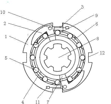
[0013] see figure 1 , an automatic overrunning clutch, comprising: a clutch outer ring 1, a throwing block 2 is arranged on the clutch outer ring 1, an elastic member 3 is connected to the throwing block 2, and the other end of the elastic member 3 is connected to the clutch On the outer ring 1, the other end of the elastic member 3 is connected to the throwing block 2, and the clutch inner ring 4 is fitted in the clutch outer ring 1, and a clutch inner ring 4 is arranged between the clutch inner ring 4 and the cl...


PUM


Abstract

The invention discloses an automatic overrun clutch. The automatic overrun clutch comprises clutch outer rings, wherein throwing blocks are arranged on the clutch outer rings and connected with elastic pieces, one end of each elastic piece is connected to the corresponding clutch outer ring, and the other end of each elastic piece is connected to the corresponding throwing block. A clutch inner ring is arranged in the clutch outer rings in a matched mode. A plurality of pin rollers are arranged between the clutch inner ring and the clutch outer rings. A retainer is arranged on the inner side of the clutch inner ring and provided with a plurality of groove bodies. One ends of the throwing blocks are arranged in the groove bodies. A limiting groove is formed in the retainer. By means of the mode, the automatic overrun clutch can run in one direction or two directions and is simple in structure, safe and reliable.

Description

technical field [0001] The invention relates to the field of clutches, in particular to an automatic overrunning clutch. Background technique [0002] The currently used overrunning clutch is a one-way overrunning clutch, which includes a small wheel inner sleeve with a limit groove. The small wheel inner sleeve is covered with a small wheel outer sleeve. The ratchet of the small wheel has a spring hole on the inner sleeve of the small wheel. The spring steel wire of the small wheel is inserted in the spring hole. The free end of the ratchet of the small wheel is in contact with the end of the spring steel wire of the small wheel. The free end of the ratchet of the small wheel The end is located outside the spring steel wire of the small wheel. The inner surface of the small wheel jacket is designed with small wheel teeth. When using this structure, the inner sleeve of the small wheel actively rotates forward, and the ratchet teeth of the small wheel are embedded in the tee...

Claims


Application Information

Patent Timeline
Patent Type & Authority Applications(China)
IPC IPC(8): F16D41/064F16D43/04
Inventor 李明阳
Owner 李明阳
Learn More