
Transverse shear digital holographic method capable of eliminating light field distortion

A transverse shearing, digital holography technology, applied in the field of digital holography, can solve the problems of low spatial frequency of fringes, complicated optical paths and devices, etc.

Active Publication Date: 2015-06-17
ZHEJIANG UNIVERSITY OF SCIENCE AND TECHNOLOGY
View PDF5 Cites 16 Cited by
  • Summary
  • Abstract
  • Description
  • Claims
  • Application Information

AI Technical Summary

Problems solved by technology

Compared with digital holography, transverse shear interference does not require reference light, but the optical path and device are more complicated than digital holography, and the obtained interference fringes contain gradient information of the wavefront to be measured, so the fringe spatial frequency is lower than that of digital holography

Method used

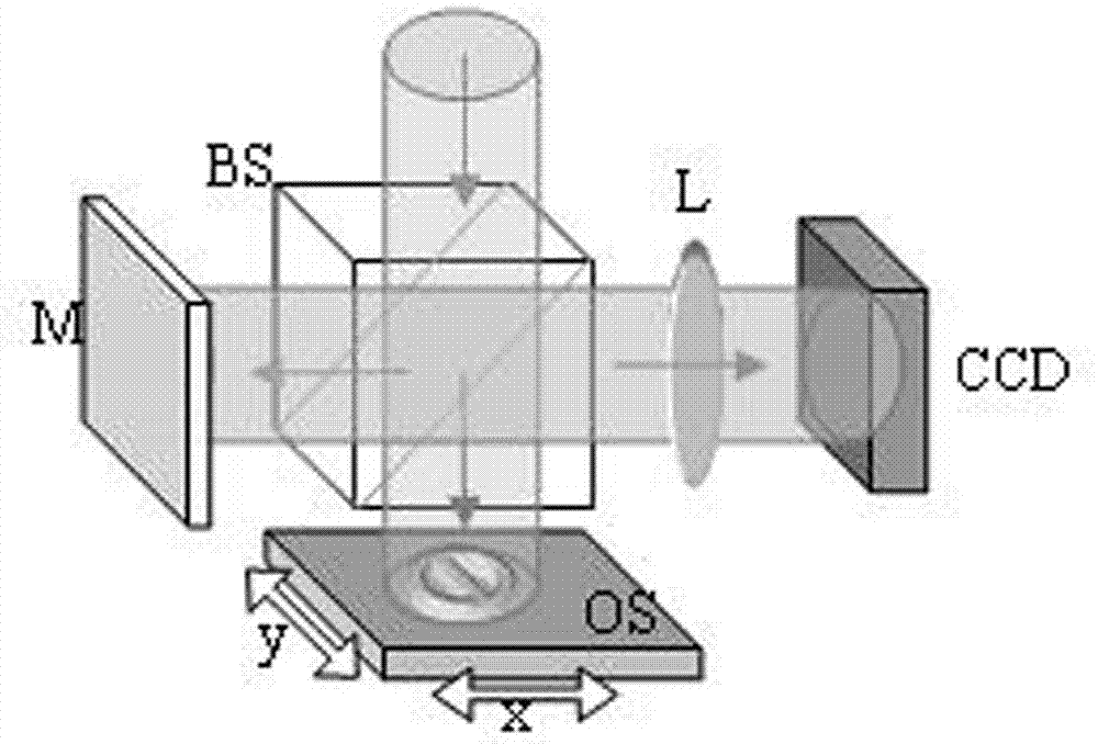
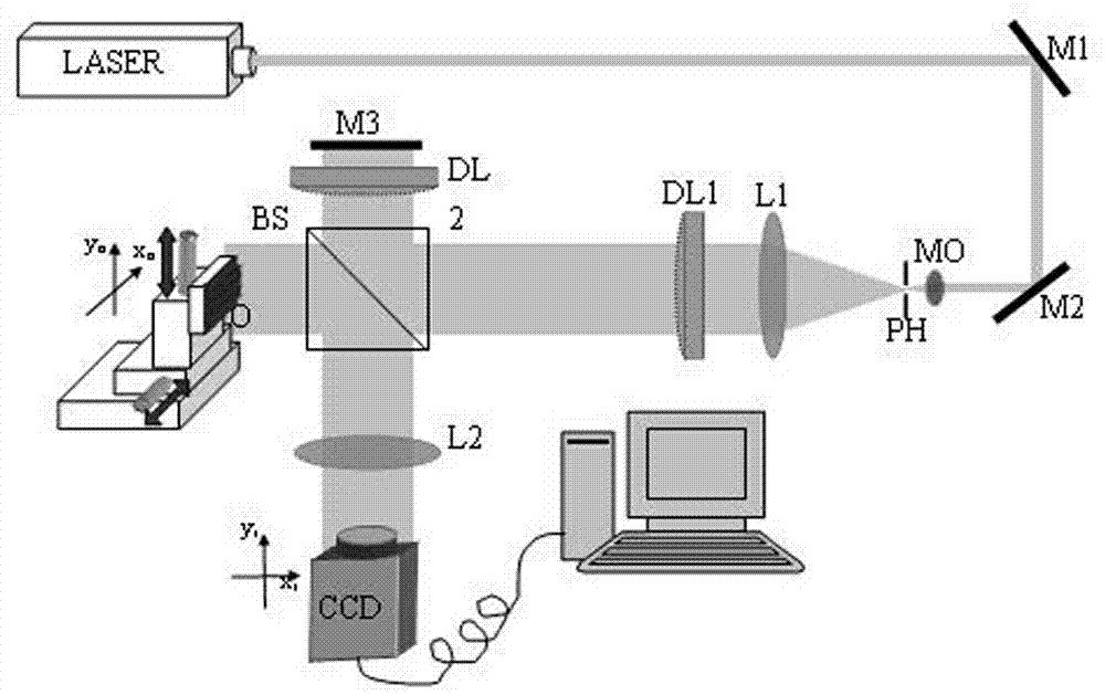
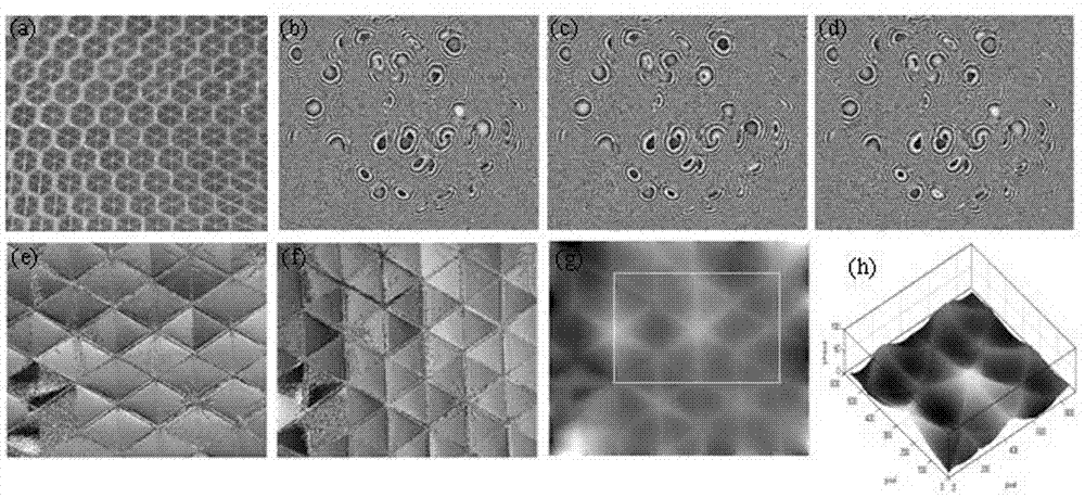

Image

  • Transverse shear digital holographic method capable of eliminating light field distortion
  • Transverse shear digital holographic method capable of eliminating light field distortion
  • Transverse shear digital holographic method capable of eliminating light field distortion

Examples


Embodiment Construction

[0047] The present invention will be described in further detail below in conjunction with the accompanying drawings, but it is not intended to limit the protection scope of the present invention.

[0048] The optical path of the object plane translation transverse shear digital holography is as follows figure 1 As shown, the incident light is divided into two beams by the beam splitter BS, one beam is incident on the mirror M as interference reference light, and the other beam is incident on the object to be measured as the object light, the object to be measured is fixed on the stage OS, and the object The stage can be translated laterally along the two orthogonal directions of x and y. The object to be measured on the stage is imaged to the CCD surface through the imaging lens L, and the object light and the reference light interfere on the CCD surface to generate an interference hologram.

[0049] Let the illumination light field incident on the surface of the object ...


PUM


Abstract

The invention discloses a transverse shear digital holographic method capable of eliminating various kinds of light field distortion. Three digital holograms with object planes mutually having tiny translation are adopted, phase distortion introduced by illuminating light and reference light is eliminated through a wavefront differential, and three-dimensional data of an object plane to be detected are recovered through the transverse shear wavefront reconstruction algorithm. A reflection-type experimental detection light path is designed, and unknown wavefront distortion is introduced into the light path so that experimental verification can be conducted on the algorithm. Results show that under the conditions that strict azimuth calibration is not conducted on the object planes or CCD recording surfaces, transverse translation precision is 0.01 mm and the translation amount is 0.02 mm, root mean square error (RMSE) of the phase in the method and a standard phase is about lambda / 19, and error sources are analyzed. The method can be used for ultra-precise optical three-dimensional measurement and has a chance of reducing the light field distortion and improving measurement precision.

Description

Technical field [0001] The present invention involves a digital holographic method, especially a horizontal cut digital holographic method that eliminates the dispersion of light fields. Background technique [0002] Digital holographic uses the optical detector and digital processing technology to obtain phase information of the light, restore the three -dimensional shape of the object, and has the advantages of three -dimensional imaging such as fast, non -destructive and high -resolution.In recent years, digital holographic technology has attracted the attention of many researchers, and has been widely used in biomedical testing [5] , Graval field measurement, appearance analysis, deformation vibration measurement and information encryption and other fields. [0003] At present, the commonly used digital holographic generally uses a bearing holographic path. The light waves are deformation by the object to be tested, and then superimposed with the reference light wave interfer...

Claims


Application Information

Patent Timeline
Patent Type & Authority Applications(China)
IPC IPC(8): G01B11/24
Inventor 潘卫清
Owner ZHEJIANG UNIVERSITY OF SCIENCE AND TECHNOLOGY
Learn More