Eureka AIR delivers breakthrough ideas for toughest innovation challenges, trusted by R&D personnel around the world.

Method for machining metal plate and mesh member produced by means of said machining method

A processing method and metal plate technology, which are applied in separation methods, chemical instruments and methods, filtration and separation, etc., can solve the problems of reduced efficiency and easy breakage of the edge 100b, and achieve high-efficiency processing, ensure design strength, and high-efficiency deep drawing processing. Effect

Active Publication Date: 2015-06-17
UCHIYAMA MFG
View PDF7 Cites 0 Cited by
  • Summary
  • Abstract
  • Description
  • Claims
  • Application Information

AI Technical Summary

Problems solved by technology

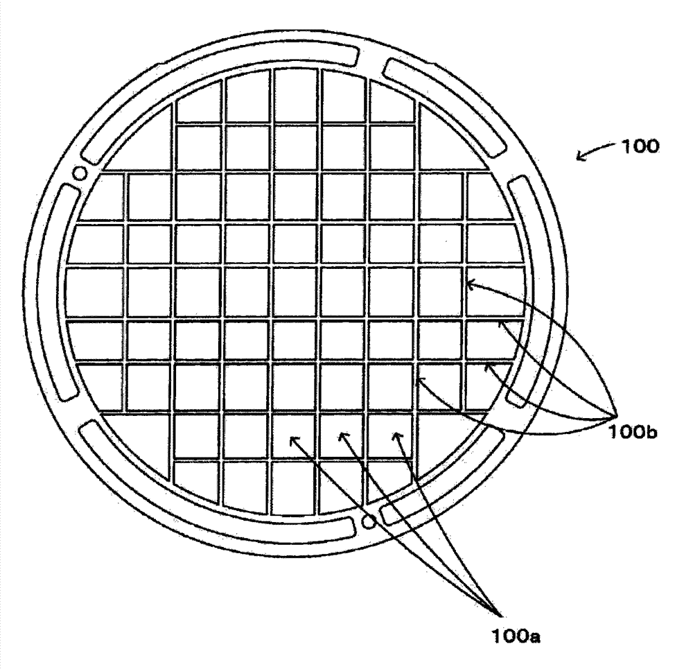
[0004] In such a case, there is a problem that the expansion force generated during drawing works on the thin line-shaped side portions 100b, 100b, thereby generating pressure, and the side portion 100b ... is easily broken.
Therefore, a working method of reducing the pressing speed at the time of drawing or forming gradually through a plurality of pressing processes has been considered, but this leads to a decrease in efficiency.

Method used


Image

  • Method for machining metal plate and mesh member produced by means of said machining method
  • Method for machining metal plate and mesh member produced by means of said machining method
  • Method for machining metal plate and mesh member produced by means of said machining method

Examples


Embodiment Construction

[0031] Hereinafter, embodiments of the present invention will be described with reference to the drawings.

[0032] In addition, in some drawings, some of the specific reference numerals attached to other drawings are omitted.

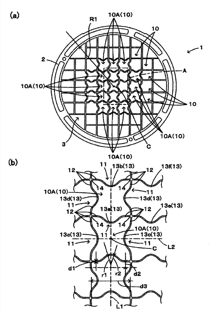
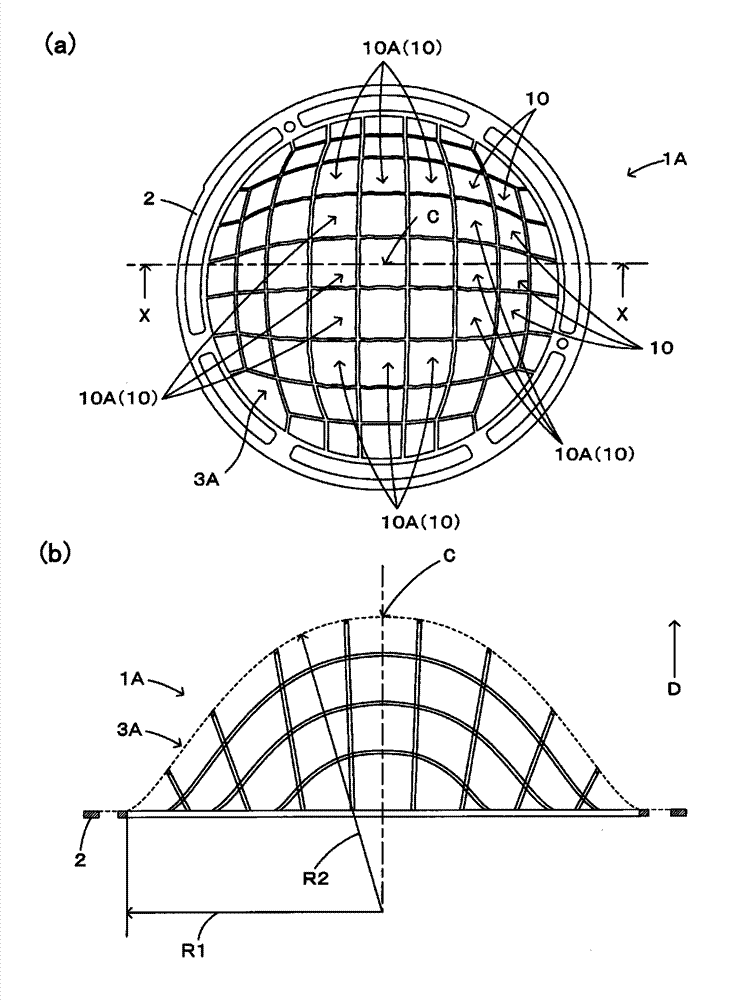
[0033] figure 1 It is a figure which schematically shows an example of the mesh body before drawing in the metal plate processing method of this embodiment, figure 2 It is a figure which schematically shows an example of the mesh member manufactured by drawing this mesh body.

[0034] The metal plate processing method of the present embodiment includes a first step of manufacturing the mesh body 1 and a second step of manufacturing the mesh member 1A by subjecting the mesh body 1 to drawing processing.

[0035] (1st process)

[0036] In this embodiment, the example which manufactured the net body 1 of the substantially circular plate shape which is substantially circular in planar view from a metal plate was shown.

[0037] As the metal plate, fo...


PUM


Abstract

This method for machining a metal plate machines into a dome shape a mesh body (1) that is made from a metal plate and at which a plurality of lattice-shaped through holes (10) have been formed, and is characterized in that when forming a mesh body provided with a plurality of sides (11) configuring the through holes by machining the metal plate, an extension allowance section (13) is formed curving in the plane-region direction at the sides of the machined region at which the mesh body is pressed in a drawing-machining, and the mesh body is machined in the dome shape by drawing-machining from one side to another side.

Description

technical field [0001] The present invention relates to a metal plate processing method for processing a mesh body composed of a metal plate having a plurality of through holes into a dome shape, and a mesh member manufactured by the processing method. Background technique [0002] Conventionally, for example, a mesh member (filter) for rectification incorporated in the middle of fluid piping is known. The mesh member is plastically processed such as drawing to form a dome shape with a raised central portion so as not to interfere with blades and the like installed in the piping. [0003] image 3 The shape of such a mesh member before processing is shown. Such a mesh member is obtained by forming a net body 100 having edge portions 100b, 100b ... of a plurality of through holes 100a forming a grid on a metal plate, and drawing the net body 100 to form a net body 100. Shape into the desired dome shape. [0004] In such a case, there arises a problem that the stretching fo...

Claims


Application Information

Patent Timeline
Patent Type & Authority Applications(China)
IPC IPC(8): B21D22/26B21D31/02
CPCB21D22/26B21D31/02B01D29/012B01D29/035B01D2239/10B01D35/02B01D39/10B01D29/0093B21D35/001
Inventor 吉田幸男葛原智德葛原康德
Owner UCHIYAMA MFG
Why Eureka
Eureka Blog
Learn More