Pneumatic automatic filing forceps machine with saw

A pneumatic and band saw technology, applied in metal sawing equipment, tool trimming of sawing machine devices, metal processing equipment, etc., can solve the problems of manual pliers easily scratching workers, uneven tooth shape, low efficiency, etc. Achieve the effects of simple structure, light strength and convenient operation

Inactive Publication Date: 2015-06-24
叶天云
View PDF6 Cites 6 Cited by
  • Summary
  • Abstract
  • Description
  • Claims
  • Application Information

AI Technical Summary

Benefits of technology

This patented technology uses an improved version of this method called 3-Tooth Cycle Automatic Trimming (CATE). It allows for more precise cutting without requiring laborious handwork by eliminating any unnecessary steps or damaging areas on the cut surface during the final step. Its technical effect includes reducing worker's burden while still maintaining good quality results from its use.

Problems solved by technology

This patented technical problem addressed by this patents relates to improving the performance or lifespan of bandsaw tools that have been affected with damage caused from sharp edges on their surfaces due to factors like abrasion, bending stress, temperature changes over repeated usage periods. To address these issues, various solutions were developed including filtration methods, plier techniques, and automatic procedures involving filings and clamps.

Method used


Image

  • Pneumatic automatic filing forceps machine with saw
  • Pneumatic automatic filing forceps machine with saw
  • Pneumatic automatic filing forceps machine with saw

Examples


Embodiment Construction

[0036] In order to further understand the content of the invention, features and functions of the present invention, in conjunction with the accompanying drawings, give an example to describe in detail as follows:

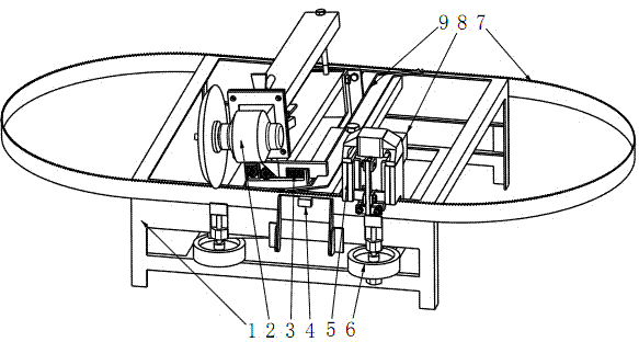
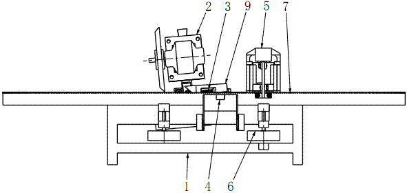
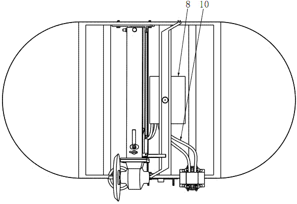
[0037] figure 1 , 2 , 3 shows the overall view of the working state of the present invention, the overall structure of the present invention consists of a machine housing 1, a tooth filing device 2, a tooth pulling mechanism 9, a tooth pliers device 5, a band saw position regulator 6 and an electrical control system 8 Composition, the upper part of the housing is provided with a file tooth device 2, a tooth pulling mechanism 9 and a tooth clamp device 5 in sequence; four band saw position regulators 6 are respectively provided on the front and rear ends of the housing, and the band saw position regulator 6 functions in And support the band saw blade 7, and adjust the position of the band saw blade 7 according to the width of the band saw blade 7 and the size of t...


PUM


Abstract

The invention belongs to woodworking machinery products and relates to a pneumatic automatic filing forceps machine, with a saw, comprising a housing, a filing tooth device, a drawing tooth mechanism, a forceps tooth device, two saw position regulators and a pneumatic and electric control system. The upper portion of the housing is provided with the filing tooth device, the drawing tooth mechanism and the forceps tooth device sequentially; the saw position regulators of the front end of the housing are installed corresponding to the filing tooth device and forceps tooth device; a conductive travel switch is connected to the pneumatic and electric control system, and the pneumatic and electric control system is connected to cylinders of the filing tooth device and forceps tooth device through air pipes; a rolling wheel of the front end of a longitudinal regulating support of the filing tooth device contacts with a triangular block of the front end of a drive block of the drawing tooth mechanism. By the triple-tooth circulation automatic tooth collecting scheme, all the correcting operations with the saw can be implemented automatically, the machine has the advantages of reasonable design, simple structure, convenience for operation and high practicality, the work intensity of saw correction can be reduced greatly for workers, and the hands of the workers are protected from scratching during manual tooth correction.

Description


Claims


Application Information

Patent Timeline
Owner 叶天云
Why Eureka
Try Eureka