Hybrid heater core system

A heater core and heater technology, applied in water heaters, air heaters, fluid heaters, etc., can solve problems such as difficult assembly, high production cost, and flow loss

Active Publication Date: 2015-06-24
HYUNDAI MOTOR CO LTD +1
View PDF6 Cites 3 Cited by
  • Summary
  • Abstract
  • Description
  • Claims
  • Application Information

AI Technical Summary

Problems solved by technology

[0003] However, since the above-mentioned structure of the related art has difficulties such as assembly and the need to integrate separate components into one air flow channel, there are problems such as difficulty in assembly, high production costs, and flow problems due to discontinuous air flow channels. Loss and other issues

Method used


Image

  • Hybrid heater core system
  • Hybrid heater core system
  • Hybrid heater core system

Examples


Embodiment Construction

[0023] Reference will now be made in detail to various embodiments of the invention, examples of which are illustrated in the accompanying drawings and described below. While the invention will be described in conjunction with exemplary embodiments, it will be understood that present description is not intended to limit the invention to those exemplary embodiments. On the contrary, the invention is intended to cover not only the exemplary embodiments but also various alternatives, modifications, equivalents and others which may be included within the spirit and scope of the invention as defined by the appended claims. implementation.

[0024] Exemplary embodiments of the present invention will be described below with reference to the accompanying drawings.

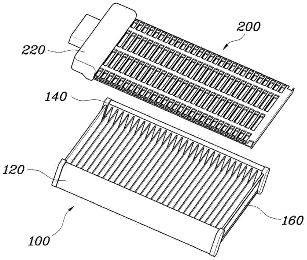
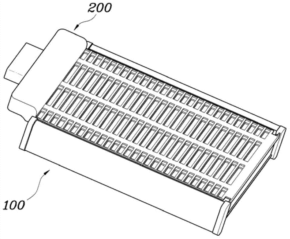
[0025] figure 1 is an exploded perspective view of a hybrid heater core system according to an exemplary embodiment of the present invention, figure 2 is a perspective view of a hybrid heater core system according to ...


PUM


Abstract

A hybrid heater core system may include a heater core body having an upper header; a lower header; and a plurality of cooling water tubes connecting the upper and lower headers; and a PTC heater coupled to the heater core body and having a PTC element; a flow path hole forming a flow path in the PTC heater; a connector formed at a first end of the PTC heater; locking protrusions configured to be locked to the upper and lower headers at upper end and lower end thereof; and a hook locked and fixed to the cooling water tubes at a second end of the PTC heater.

Description

technical field [0001] The present invention relates to a hybrid heater core system capable of integrating heater cores and PTC heaters in the related art by simply locking and assembling these elements, while maximizing heating performance through an optimized structure change. Background technique [0002] For effective response of heating performance, in the related art, a heater core and a PTC heater using engine cooling water are used simultaneously. Therefore, in the related art, individual PTC heaters are provided in front of the heater core to achieve continuous arrangement by respective fixing structures. [0003] However, since the above-mentioned structure of the related art has difficulties such as assembly and the need to integrate separate components into one air flow channel, there are problems such as difficulty in assembly, high production costs, and flow problems due to discontinuous air flow channels. loss etc. [0004] The information disclosed in the ...

Claims


Application Information

Patent Timeline
Patent Type & Authority Applications(China)
IPC IPC(8): B60H1/00
CPCF24H3/0429F24H3/0458F24H3/12F24H9/1872F24H2250/06F28D1/0435F28D1/05366B60H1/00328B60H1/034B60H1/2225H05B2203/02H05B2203/023F24H1/105F24H1/106
Inventor 金明会金仁奎丘重三
Owner HYUNDAI MOTOR CO LTD
Why Eureka
Try Eureka