
Assembly concrete new type pillar and beam structure and assembly connecting method

A technology for concrete and beam structures, which is applied in the field of beam structures and assembly connections, as well as in the field of prefabricated concrete new columns, which can solve the problems of inability to realize shear connections such as prefabricated columns, large amount of connection sleeves, and high project cost, so as to reduce the quantity, The effect of economical connection and reliable connection

Inactive Publication Date: 2015-06-24
SHENYANG JIANZHU UNIVERSITY
View PDF8 Cites 30 Cited by
  • Summary
  • Abstract
  • Description
  • Claims
  • Application Information

AI Technical Summary

Problems solved by technology

[0003] The purpose of the present invention is to provide a new type of prefabricated concrete column and beam structure and assembly connection method, to solve the concrete non-connection measures at the connection interface between prefabricated columns and prefabricated columns in the prior art, and the equal shear connection between prefabricated columns cannot be realized The amount of connecting sleeves between prefabricated beams and prefabricated columns is large, the project cost is high, and the connection between prefabricated beams and prefabricated concrete floors, there are no measures to fix the prefabricated concrete floors to the prefabricated beams, etc.

Method used


Image

  • Assembly concrete new type pillar and beam structure and assembly connecting method
  • Assembly concrete new type pillar and beam structure and assembly connecting method
  • Assembly concrete new type pillar and beam structure and assembly connecting method

Examples


Embodiment Construction

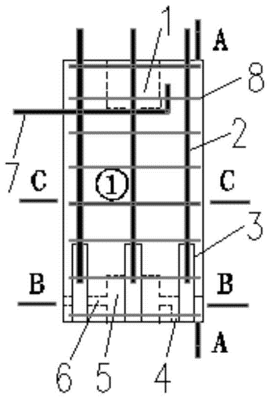
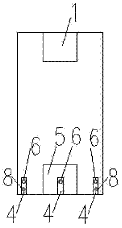
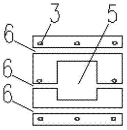
[0046] Such as Figure 1-Figure 4 As shown, the prefabricated side column of the present invention ①: the top is provided with column top grouting groove 1; the interior is equipped with column longitudinal reinforcement 2, and the lower end of column longitudinal reinforcement extends into column sleeve 3; the bottom is provided with column bottom grouting groove 5, and the outer side of the bottom The side column piercing groove 4 is provided, and the top of the side column piercing groove 4 is provided with the beam piercing steel hole 6 through the column; The butt joint reinforcement 7 extends to one end of the prefabricated side column ① and bends along the outside of the grouting groove 1 on the top of the column, and the other end of the side column is reserved to connect with the steel bar at the bottom of the beam 7 extends out of the prefabricated side column ① along the transverse direction; along the prefabricated side column ① In the height direction, there are c...


PUM


Abstract

The invention relates to the field of assembly concrete buildings, in particular to an assembly concrete new type pillar and beam structure and an assembly connecting method. Assembly concrete new type pillars and an assembly concrete new type beam can serve as pillars and a beam applied to the assembly concrete buildings. The assembly concrete new type pillar and beam structure comprises a prefabricated pillar and prefabricated beam structure, and each prefabricated pillar comprises a prefabricated side pillar and a prefabricated center pillar. Grouting grooves are formed in the top and the bottom of each prefabricated pillar, and the connected grouting grooves are grouted with a grouting material to achieve equal-shearing-strength connection between the prefabricated pillars; as beam steel bar penetrating holes are reserved in the prefabricated pillars, prefabricated beam steel bars can directly penetrate through the prefabricated pillars to be connected with the prefabricated pillars; as steel poles provided with threads at the ends are pre-buried in the prefabricated beam to transmit shearing force and pull force between the prefabricated beam and post-poured concrete, and the steel poles with the threads at the ends can serve as connecting pieces for fixing a prefabricated slab to the prefabricated beam. By the adoption of the method, connection between precast concrete members is more reliable and economical.

Description

technical field [0001] The invention relates to the field of prefabricated concrete buildings, in particular to a novel prefabricated concrete column and beam structure and an assembly connection method. The prefabricated concrete novel post and beam structure can be used as columns and beams used in prefabricated concrete buildings. Background technique [0002] At present, in the actual prefabricated concrete building: the connection between prefabricated concrete columns and precast concrete columns (hereinafter referred to as prefabricated concrete columns for short, prefabricated The method of pouring grout in the sleeve is used to connect the longitudinally stressed steel bars in the precast column without connecting the concrete at the interface of the precast column, and the equal shear connection between the precast column and the precast column cannot be realized; the connection between the precast column and the precast concrete beam (hereinafter referred to as pr...

Claims


Application Information

Patent Timeline
IPC IPC(8): E04B1/20E04B1/21E04G21/00
Inventor 李明赵唯坚张沛楠郝艳婷
Owner SHENYANG JIANZHU UNIVERSITY
Learn More