Ceramic valve

A technology of ceramic valve and casing, applied to ceramic valve. It can solve the problems of low production yield, solenoid valve and switching valve can not work, can not be flushed, etc., to achieve the effect of improving service life, reducing pressure and reducing failure rate

Inactive Publication Date: 2015-06-24
张丽军
View PDF10 Cites 7 Cited by
  • Summary
  • Abstract
  • Description
  • Claims
  • Application Information

AI Technical Summary

Problems solved by technology

[0002] In the prior art, the water route of most smart toilets or smart toilet lids is controlled by solenoid valves and switching valves. Since the solenoid valves and switching valves are limited by the power supply, once the power is cut off, the solenoid valves and switching valves will not work, resulting in a power failure. The problem of not being able to flush
In addition, the solenoid valve is greatly affected by the water quality. There are many impurities in the water, which will cause the solenoid valve to malfunction and cannot be closed normally, causing the nozzle to drip and be wasted. The failure rate is about 15-25%, which not only affects the normal use of consumers , and greatly increase the manufacturer's after-sales burden
A small number of smart toilets or toilet lids are controlled by ceramic valves, but this ceramic valve adopts a bottom water inlet structure. This structure has a low production yield and is easy to leak water into the toilet or toilet lid. Can't rotate and many other problems

Method used


Image

  • Ceramic valve
  • Ceramic valve
  • Ceramic valve

Examples


Embodiment 1

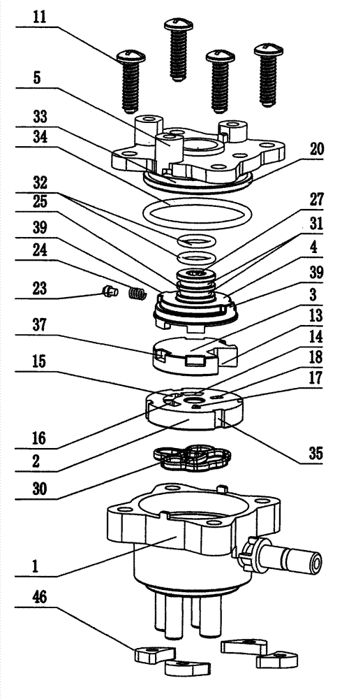
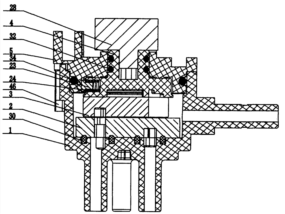
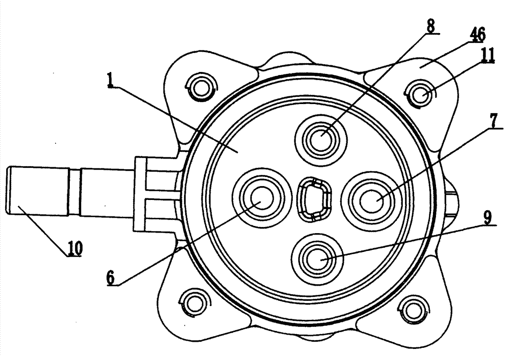
[0037] As an embodiment of the ceramic valve of the present invention, such as figure 1 , figure 2 , image 3 , Figure 4 , Figure 5 , Figure 6 , Figure 7 and Figure 8As shown, it includes a housing 1, a fixed piece 2, a moving piece 3, a dial 4 and a gland 5. The bottom surface of the housing 1 is provided with a cold water outlet pipe 6, a hot water inlet pipe 7, a first cleaning pipe 8 and The second cleaning pipe 9 is provided with a cold water inlet pipe 10 on the side wall of the housing 1, the fixed piece 2 is arranged inside the housing 1, and is positioned with the housing 1 on the radial upper limit, and the The moving piece 3 is arranged above the fixed piece 2, the dial 4 is arranged above the moving piece 3, and is positioned on the radial upper limit with the moving piece 3, and the gland 5 is arranged on the dial 4 above, connected with the housing 1 by bolts 11, and then fixed by arc nuts 46, the lower surface of the moving piece 3 is provided with ...

Embodiment 2

[0048] As an embodiment of the ceramic valve of the present invention, such as Figure 9 and Figure 10 As shown, the difference from Embodiment 1 is that in this embodiment, the ceramic valve also includes a motor 41, a driving wheel 42 and a driven wheel 43, and a fixed rod 25 is arranged on the upper surface of the dial 4, and the The gland 5 is provided with a socket 26, the upper end of the fixed rod 25 is inserted into the socket 26, the center of the fixed rod 25 is provided with a slot 27, and the driven wheel 43 is located in the slot 27 , the driving wheel 42 is connected to the output end of the motor 4, and the driving wheel 42 and the driven wheel 43 are meshed. The drive wheel 42 and the driven wheel 43 are provided with a gear box 44 outside, the gear box 44 is fixed on the upper surface of the gland 5 by two self-tapping screws 45, and the motor 41 is fixed on the upper surface of the gland 5 by two self-tapping screws. 47 is fixed on the upper surface of the...


PUM


Abstract

The invention relates to the technical field of valves, in particular to a ceramic valve. The ceramic valve comprises a shell, a stator plate, a rotor plate, a drive plate and a gland, wherein a cold water outlet pipe, a hot water inlet pipe, a first cleaning pipe and a second cleaning pipe are arranged on the bottom surface of the shell, a cold water inlet pipe is arranged on the side wall of the shell, the stator plate is arranged in the shell and is used for limiting in the radial direction together with the shell, the rotor plate is arranged above the stator plate, the drive plate is arranged above the rotor plate and is used for limiting in the radial direction together with the rotor plate, the gland is arranged above the drive plate and is connected with the shell through bolts and nuts, a first groove is formed in the lower surface of the rotor plate, an opening is formed in the portion, symmetrical to the first groove, of the edge of the rotor plate, and a first through hole, a second through hole, a third through hole, a fourth through hole and a fifth through hole are formed in the stator plate.

Description

technical field [0001] The invention relates to the technical field of valves, in particular to a ceramic valve. Background technique [0002] In the prior art, the water route of most smart toilets or smart toilet lids is controlled by solenoid valves and switching valves. Since the solenoid valves and switching valves are limited by the power supply, once the power is cut off, the solenoid valves and switching valves will not work, resulting in a power failure. The problem of not being able to rinse. In addition, the solenoid valve is greatly affected by the water quality. There are many impurities in the water, which will cause the solenoid valve to malfunction and cannot be closed normally, causing the nozzle to drip and be wasted. The failure rate is about 15-25%, which not only affects the normal use of consumers , and greatly increase the manufacturer's after-sales burden. A small number of smart toilets or toilet lids are controlled by ceramic valves, but this cera...

Claims


Application Information

Patent Timeline
Patent Type & Authority Applications(China)
IPC IPC(8): F16K11/072F16K31/04F16K31/53F16K31/60
CPCF16K11/074F16K31/043F16K31/055F16K31/53
Inventor 张丽军
Owner 张丽军
Why Eureka
Try Eureka