Display system and control method

A display system and control method technology, applied to static indicators, optics, instruments, etc., can solve the problems of incomplete anti-peeping methods and inability to prevent them

Active Publication Date: 2015-06-24
BOE TECH GRP CO LTD
View PDF4 Cites 44 Cited by
  • Summary
  • Abstract
  • Description
  • Claims
  • Application Information

AI Technical Summary

Problems solved by technology

The above anti-peeping method is not thorough, and cannot prevent other people from watching in the same direction

Method used


Image

  • Display system and control method
  • Display system and control method
  • Display system and control method

Examples


Embodiment 1

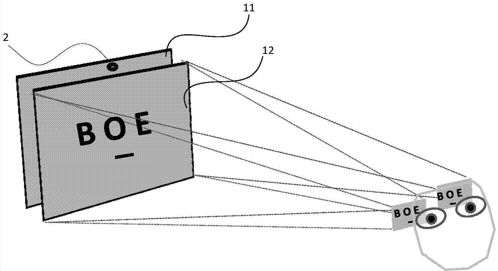
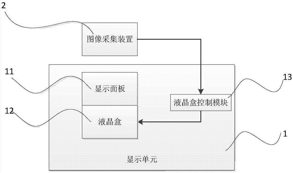
[0074] Such as figure 1 As shown, the present invention provides a kind of display system, and this display system comprises: display unit 1, image acquisition device 2; 1 also includes a liquid crystal box control module 13; the image acquisition device 2 acquires the image in front of the display unit 1, and transmits it to the liquid crystal box control module 13; the liquid crystal box control module 13 recognizes a predetermined face in the image, and according to the predetermined face in the image The position determines the specific area where the predetermined face is located, and outputs a control signal to the liquid crystal cell 12 according to the specific area, and the liquid crystal cell 12 controls the light emitted from the display panel 11 through the liquid crystal cell 12 to the specific area according to the control signal. The display system provided by the present invention will be described in detail below.

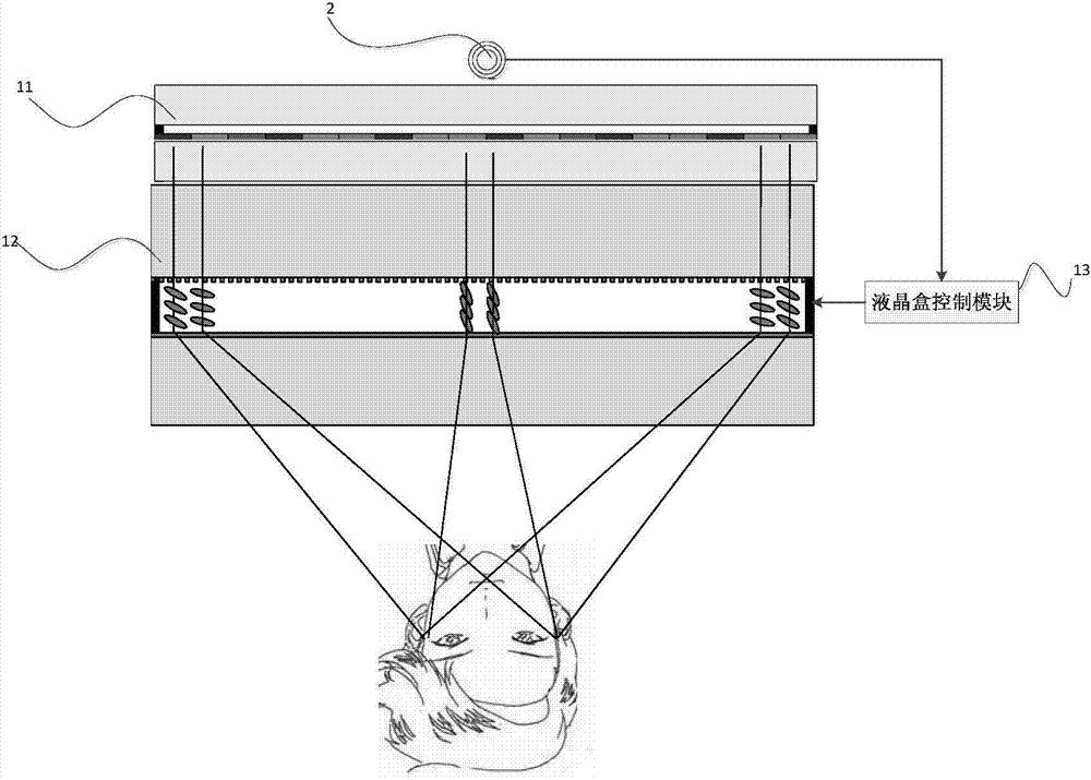
[0075] Such as figure 2 , image 3 As sh...

Embodiment 2

[0081] The inventors have found through studying the scheme of Embodiment 1 that two sets of strip electrodes 1241 and 1242 arranged on the first substrate 121 and / or the second substrate 122 with extending directions perpendicular to each other are difficult to control during display. The present invention reduces the difficulty of controlling the electrodes by arranging two layers of liquid crystal cells in front of the display panel 11 . Specifically, such as Figure 16 As shown, this embodiment is basically the same as the solution of Embodiment 1, except that a first liquid crystal cell for controlling light emission in the horizontal direction and a second liquid crystal cell for controlling light emission in the vertical direction are arranged in front of the display panel. The display unit 1 also includes a liquid crystal cell control module 13 ; The liquid crystal cell control module 13 recognizes a predetermined human face in the image, determines a predetermined ar...

Embodiment 3

[0086] This embodiment is basically the same as Embodiment 1, the difference is that, as Figure 17 As shown, the plurality of electrodes disposed on the first substrate 121 and / or the second substrate 122 are point electrodes 124 . Such as Figure 18 As shown, each dot electrode 124 includes a plurality of sub-electrodes 1240 , and each sub-electrode 1240 of each dot electrode 124 is individually applied with a driving voltage during display, so that the strength of deflection electric fields in adjacent liquid crystal deflection regions is different. In the present invention, the liquid crystal molecules in each deflection area can be accurately controlled to deflect horizontally and / or vertically according to corresponding control commands through the point electrodes 124, so that the light passing through each liquid crystal area can be accurately emitted to a predetermined area.


PUM


Abstract

The invention discloses a display system and a control method. The display system comprises a display unit and an image collection device. The display unit comprises a display panel and a liquid crystal box arranged in the light emitting direction of the display panel. The display unit further comprises a liquid crystal box control module. The image collection device acquires an image in front of the display unit and transmits the image to the liquid crystal box control module. The liquid crystal box control module recognizes a reserved face in the image, determines a specific region where the reserved face is located according to the position of the reserved face in the image and outputs a control signal to the liquid crystal box according to the specific region, and the liquid crystal box controls light transmitting into the liquid crystal box from the display panel to be emitted to the specific region according to the control signal. The display system collects the image in front of the display unit, performs face recognition to determine the specific region where the reserved face is located and adjusts the direction of emergent light transmitting through the liquid crystal box, thereby enabling only the reserved face to see the displayed image, and preventing non-reserved objects in other regions from peeping at the image.

Description

technical field [0001] The invention relates to a display system and a control method, and belongs to the technical field of peep-proof display. Background technique [0002] Due to the increasing popularity of electronic information devices, people rely more and more on using electronic information devices to handle affairs. In order to protect the privacy of information from being peeped by others, people pay more and more attention to the security protection of information. Therefore, various anti-peeping devices are widely used in electronic information devices. In earlier anti-peeping technologies, anti-peeping devices mostly use anti-peeping sheets attached to the surface of the screen to achieve the anti-peeping function. The user sticks the anti-spy sheet on the screen in an environment where there are other people, so as to prevent others from seeing the information on the screen from around the user. When the user is using the electronic information device alone...

Claims


Application Information

Patent Timeline
Patent Type & Authority Applications(China)
IPC IPC(8): G06F21/84G06F21/32G02F1/13G02F1/133
CPCG02F1/1347G09G3/3406G09G3/3696G09G2320/0626G09G2320/0686G09G2320/08G09G2354/00G09G2358/00
Inventor 魏伟
Owner BOE TECH GRP CO LTD
Why Eureka
Try Eureka