
A Broadband Bandpass Filter with Reconfigurable Frequency and Bandwidth

A band-pass filter and bandwidth technology, applied in waveguide devices, electrical components, circuits, etc., can solve problems such as no grounding point, limited performance, and difficult design, achieve good electromagnetic compatibility, and overcome narrow bandwidth , to achieve the effect of electrical reconfigurability

Inactive Publication Date: 2017-06-06
SOUTH CHINA UNIV OF TECH
View PDF6 Cites 2 Cited by
  • Summary
  • Abstract
  • Description
  • Claims
  • Application Information

AI Technical Summary

Problems solved by technology

Most of the published existing technologies are designed based on narrowband filters, which cannot meet the needs of wideband reconfigurable communication systems. For wideband reconfigurable filters, the proposed methods and structures and the achieved performance are limited.
In addition, when the active device is loaded on the open resonator, the microstrip structure will inevitably introduce ground vias when combined with the active device. For the short-circuit resonator, the design of the active device is straightforward and simple, but some In order to achieve better performance and smaller size, the open circuit resonator should be given priority. Since it does not have a grounding point, the design is relatively difficult

Method used


Image

  • A Broadband Bandpass Filter with Reconfigurable Frequency and Bandwidth
  • A Broadband Bandpass Filter with Reconfigurable Frequency and Bandwidth
  • A Broadband Bandpass Filter with Reconfigurable Frequency and Bandwidth

Examples


Embodiment 1

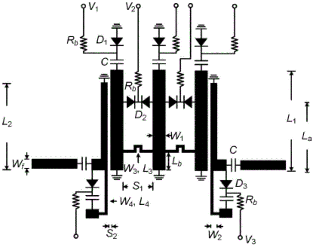
[0037] like Figure 5 As shown, the microstrip line structure 1 and active circuit of the upper layer of the broadband bandpass filter of this embodiment, the dielectric substrate 2 of the middle layer, the grounding metal patch (not shown in the figure) and the metal via hole of the lower layer, the The metal through holes sequentially pass through the microstrip line structure 1, the dielectric substrate 2 and the ground metal patch. The microstrip line structure 1 includes the first port feeder 3, the second port feeder 4, the first resonator and the second resonator The first port feeder 3 and the second port feeder 4 are bilaterally symmetrical, the left end of the first port feeder 3 is used as the input port Port1, the right end of the second port feeder 4 is used as the output port Port2, and the first port feeder 4 is used as the output port Port2. The resonator is arranged above the first port feeder 3 and the second port feeder 4, the second resonator is arranged be...

Embodiment 2

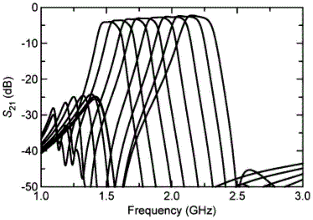
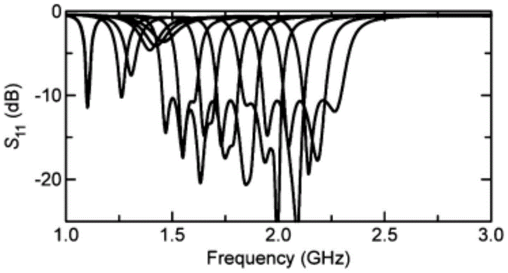
[0047] like Figure 5 As shown, by loading varactor diodes on the transmission lines and stubs of the two T-shaped resonators (the first resonator and the second resonator), the odd-mode and even-mode resonant frequencies can be independently controlled to achieve a frequency and bandwidth All reconfigurable wideband bandpass filters (also known as fully tunable wideband bandpass filters) with independently tuneable center frequency and absolute bandwidth. The circuit and electromagnetic simulation software of this embodiment is Agilent Advanced Design System (ADS). The broadband bandpass filter with reconfigurable frequency and bandwidth is chosen to be processed on a dielectric substrate with a dielectric constant of 2.55, a thickness of 0.8mm, and a loss tangent of 0.0029. The specific physical dimensions are shown in Table 1 below.

[0048]

[0049] Table 1 Dimensions of wideband bandpass filters with reconfigurable frequency and bandwidth

[0050] This embodiment is ...


PUM


Abstract

The invention discloses a broadband bandpass filter with reconfigurable frequency and bandwidth, which comprises an upper layer microstrip line structure and an active circuit, a middle layer dielectric substrate, a lower layer grounded metal patch, and metal through holes. The holes pass through the microstrip line structure, the dielectric substrate and the grounding metal patch in turn, so that the microstrip line structure and the grounding metal patch are connected through the dielectric substrate. The microstrip line structure includes the first port feeder, the second port feeder, The first resonator and the second resonator, the first port feeder and the second port feeder are bilaterally symmetrical, the first resonator is arranged above the first port feeder and the second port feeder, and the second resonator is arranged on Below the feeder line for the first port and the feeder line for the second port, the entire microstrip line structure is in the shape of a "cross". The frequency and bandwidth of the present invention can be independently reconfigured, and there is a transmission zero point on both sides of the passband, which improves the rectangularity and selectivity of the filter, and the overall performance is good.

Description

technical field [0001] The invention relates to a broadband bandpass filter, in particular to a broadband bandpass filter with reconfigurable frequency and bandwidth applied in a broadband front-end system, belonging to the technical field of microwave communication. Background technique [0002] With the continuous development of modern wireless communication technology, the RF front-end often needs to integrate multiple wireless channels and communication standards. These wireless channels and communication standards not only have different center frequencies, but also have different bandwidth requirements. This requires a reconfigurable RF front-end with both frequency and bandwidth adjustment capabilities. Traditional tuning filters cannot freely adjust the bandwidth and cannot adapt to the requirements of modern wireless systems. For this reason, a filter with the ability to adjust the center frequency and bandwidth at the same time was proposed. Its English name is fu...

Claims


Application Information

Patent Timeline
Patent Type & Authority Patents(China)
IPC IPC(8): H01P1/20H01P1/203
Inventor 褚庆昕陈志涵
Owner SOUTH CHINA UNIV OF TECH
Learn More