Space camera flutter analysis method based on target image

A space camera and flutter analysis technology, applied in image communication, television, electrical components, etc., can solve the problems of small satellite flutter amplitude, space camera image relationship, high frequency, etc., to achieve easy implementation, engineering application, Simple way to achieve the effect

Inactive Publication Date: 2015-06-24
AEROSPACE DONGFANGHONG SATELLITE
View PDF2 Cites 15 Cited by
  • Summary
  • Abstract
  • Description
  • Claims
  • Application Information

AI Technical Summary

Problems solved by technology

[0004] However, none of the above methods can intuitively reflect the impact of flutter on the imaging quality of space cameras. To know the impact of flutter on images, the most intuitive way is to obtain the pixel offset caused by satellite flutter, that is, image motion
The analysis of the impact of satellite flutter on images in the ground environment has not yet started in China, and there are few reports abroad
The main problems of directly analyzing the image motion deviation in the satellite flutter test are: (1) The commonly used surface-mounted acceleration sensor method can only get the flutter response and cannot establish a relationship with the space camera image affected by the flutter; (2) The transfer characteristic test of satellite flutter measurement can only analyze the path from the flutter source to the space camera body, and cannot establish the flutter impact analysis from the flutter source to the camera focal plane; (3) The satellite flutter amplitude is small, the frequency is high, and the space How to accurately measure the image motion of the camera in the ground test; (4) How to design the image motion deviation measurement method based on the requirements of satellite reliability and safety, as well as the characteristics of satellites that cannot be repaired

Method used


Image

  • Space camera flutter analysis method based on target image
  • Space camera flutter analysis method based on target image
  • Space camera flutter analysis method based on target image

Examples


Embodiment Construction

[0030] Below in conjunction with accompanying drawing and specific embodiment the present invention is described in further detail:

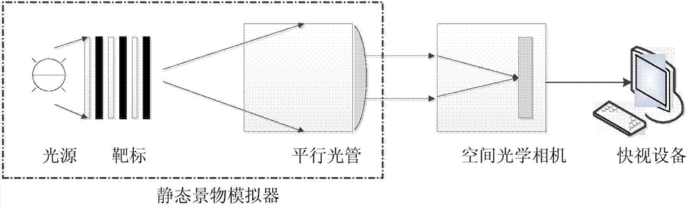
[0031] like figure 1 Shown is a schematic diagram of a space camera flutter test system for a target image of the present invention, the system includes a scene simulator, a space camera and a quick-view device, wherein the scene simulator includes a collimator and a light source. Among them, the focal length of the collimator is not less than 3 times the focal length of the space camera, and the optical aperture is larger than that of the space camera; the color temperature of the light source is not lower than 3000K, the uniformity is better than 2%, the stability is better than 1%, and the maximum radiance is for the space The output of the camera is generally not lower than 0.6 times the saturated output of the camera.

[0032] Targets should meet the following requirements:

[0033] (a) The target is a black and white bar-shaped high-cont...


PUM


Abstract

The invention relates to a space camera flutter analysis method based on a target image. The method comprises the steps that an imaging system is built at first, black and white rectangular targets comprising the specific space frequency and high contrast are placed on a collimator focal plane, the targets are illuminated by a high-stability uniform light source to be used as object targets, and are imaged on a camera focal plane through a collimator and a space camera to form clear target images, the gray scale centroid method is adopted for analysis, and an accurate image shift deflection amount is obtained. According to the space camera flutter analysis method, image analysis is combined with the optical measurement fundamental, the image shift is directly measured on an image, the influence of flutter on space camera imaging is directly analyzed, the image shift deflection amount is obtained for the first time, the gap in the prior art is filled, and the basis is provided for analyzing the influences on satellite imaging quality and finally improving and maintaining the satellite imaging quality.

Description

technical field [0001] The invention relates to a space camera flutter analysis method based on a target image, in particular to a space camera flutter impact analysis method based on image centroid position changes, and belongs to the technical field of satellite flutter testing. Background technique [0002] During the in-orbit imaging of satellites, various motion effects of moving parts on the satellite will cause the camera's boresight to vibrate relative to the observation target, thereby affecting the image quality. This component in the jitter response that cannot be measured and suppressed by the control system is called flutter response. The main reasons for camera flutter during space photography include: movement on the satellite platform due to variable speed rotation of the momentum wheel, jet, pointing control, and solar panel adjustment. For the CCD device, the basic premise of its normal operation is that the transfer of photogenerated charge packets is syn...

Claims


Application Information

Patent Timeline
Patent Type & Authority Applications(China)
IPC IPC(8): H04N17/00
Inventor 叶钊曹启鹏朱军董小静尹欢
Owner AEROSPACE DONGFANGHONG SATELLITE
Why Eureka
Try Eureka