Air Blade And Air-blade Wheel

An air knife and air knife technology, which is used in mixers, water/sludge/sewage treatment, animal husbandry, etc., can solve the problems of energy consumption and large resistance, and achieve the effect of increasing the amount of air

Inactive Publication Date: 2015-07-01
崔汇文
View PDF5 Cites 1 Cited by
  • Summary
  • Abstract
  • Description
  • Claims
  • Application Information

AI Technical Summary

Problems solved by technology

However, the blade configured in the above-mentioned device is a porous plate, so when it slaps the water and lifts it up, the resistance is very large, and a lot of energy needs to be consumed

Method used


Image

  • Air Blade And Air-blade Wheel
  • Air Blade And Air-blade Wheel
  • Air Blade And Air-blade Wheel

Examples


Embodiment Construction

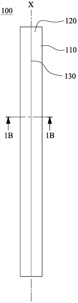
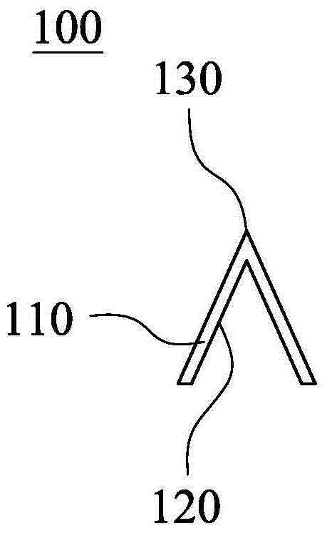
[0032] Please refer to Figure 1A and Figure 1B ,in Figure 1A is a schematic diagram of an air knife 100 according to an embodiment of the present invention, Figure 1B for Figure 1A A cross-sectional view of the air knife 100 according to the embodiment along the section line 1B-1B. Depend on Figure 1A and Figure 1B It can be seen that the air knife 100 includes a body 110 , an air channel 120 and a water-repellent structure 130 .

[0033] The body 110 is a long column with a central axis X.

[0034] The air channel 120 is located on one side of the body 110 and is parallel to the central axis X of the body 110 . Depend on Figure 1B It can be seen that in this embodiment, the air channel 120 is a V-shaped channel, and one side of the main body 110 cooperates with the air channel 120 to form a V-shaped channel, and the other side forms a V-shaped protrusion.

[0035] The aforementioned V-shaped protrusion formed on the other side of the main body 110 is the water-re...


PUM


Abstract

An air blade is provided. The air blade includes a body, an airflow channel and an anti-resistance structure. The body has a central axis. The airflow channel is located on one side of the body, and is parallel to the central axis of the body. The anti-resistance structure is located on the other side of the body, and corresponds to the airflow channel.

Description

technical field [0001] The invention relates to an air knife wheel and an air knife, and in particular to an air knife wheel and an air knife applied to an aeration water wheel for aquaculture. Background technique [0002] Most of the current fish ponds use waterwheel aerators or impeller waterwheels, which use water wheels with porous water-feeding blades, and the water-feeding blades are transferred from the water surface to the water surface and then out of the water surface so that they are continuously circulated Agitate the water to increase the amount of air incorporated into the water. Yet the blade that is configured in the above-mentioned device is a porous plate, so when it beats the water and picks up the water again, the resistance is very large, and a lot of energy needs to be consumed. Contents of the invention [0003] The object of the present invention is to provide an air knife and an air knife wheel, wherein the air knife wheel is provided with an air...

Claims


Application Information

Patent Timeline
Patent Type & Authority Applications(China)
IPC IPC(8): A01K63/04
CPCB01F2003/04567B01F3/04539A01K63/042B01F23/234211C02F3/16B01F27/80B01F27/0721B01F27/0727B01F27/11251
Inventor 崔汇文
Owner 崔汇文
Why Eureka
Try Eureka