
Spraying mechanism for spraying vehicle and spraying vehicle

A technology of spraying vehicles and spraying arms, applied in the direction of spraying vehicles, etc., can solve the problems of left and right shaking of spraying arms, waste of liquid, and manual control of spraying.

Active Publication Date: 2015-07-01
ORDOS SHENDONG TIANLONG CHEM
View PDF8 Cites 13 Cited by
  • Summary
  • Abstract
  • Description
  • Claims
  • Application Information

AI Technical Summary

Problems solved by technology

[0003] 1. The rotation angle and movement stroke positioning of the spray boom are inaccurate, and the range of rotation and movement is small, and the spraying of the spray arm needs manual control and cannot be adjusted automatically
Therefore, the efficiency of the spraying operation is low, the spraying effect is poor, and unnecessary liquid waste is caused.
[0004] 2. The supporting spray boom device mostly adopts a support frame without lifting ability, or a scissor lift, or a folding lifting mechanism for lifting adjustment, so the spray arm will shake left and right during the operation, which is unstable and poses a safety hazard
[0005] 3. Since the feeding pipeline for the spray boom needs to move with the position of the spray boom, the connection method of the soft rubber hose is often used, which is very easy to cause twisting and winding of the soft hose, aging and rupture, resulting in liquid leakage
[0006] 4. The existing spraying vehicles can only spray one kind of liquid, and the function is single. If it is necessary to spray various liquids such as dust suppressant and antifreeze on the coal column, it needs to be equipped with multiple spraying vehicles, and it cannot be done on the same machine. Work on the vehicle, resulting in a substantial increase in costs

Method used


Image

  • Spraying mechanism for spraying vehicle and spraying vehicle
  • Spraying mechanism for spraying vehicle and spraying vehicle
  • Spraying mechanism for spraying vehicle and spraying vehicle

Examples


Embodiment Construction

[0073] Specific embodiments of the present invention will be described in detail below in conjunction with the accompanying drawings. It should be understood that the specific embodiments described here are only used to illustrate and explain the present invention, and are not intended to limit the present invention.

[0074] In the present invention, in the case of no contrary description, the orientation words used such as "upper, lower, bottom, top" are defined in the normal operation of the spray truck provided by the present invention, specifically refer to Figure 1 to Figure 4 The directions shown in the drawing, and "inner and outer" refer to the inside and outside of the contour of the corresponding components, and these orientation words are only used to illustrate the present invention, and are not used to limit the present invention.

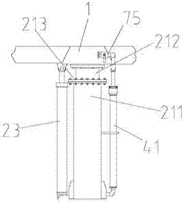
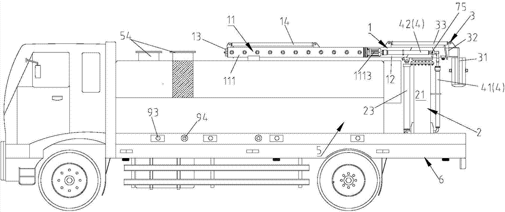
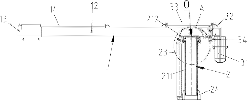
[0075] Such as Figure 1 to Figure 8 As shown, generally, the present invention provides a spraying vehicle, which comprises a veh...


PUM


Abstract

The invention discloses a spraying mechanism for a spraying vehicle, and the spraying vehicle with the spraying mechanism. The spraying vehicle comprises a vehicle chassis, and the spraying mechanism is mounted on the vehicle chassis and comprises a spraying arm with a spraying device and a rotary lifting device for supporting the spraying arm. The rotary lifting device comprises a lifting stand column, a first driving device and a second driving device; and the lifting stand column extends in the vertical direction, the first driving device drives the lifting stand column to carry out rotation, and the second driving device drives the lifting stand column to stretch out and draw back. The lifting stand column comprises a fixed column and a lifting column, and the fixed column is sleeved with the lifting column together; and the spraying arm is arranged on the lifting column which can move along the fixed column. Therefore, the spraying arm can be driven by the first driving device to rotate and driven by the second driving device to ascend and descend; the spraying work angle and the spraying work range are ensured, and meanwhile, control is convenient, and the corresponding motion stroke and locating precision can be effectively ensured; and in addition, due to the fact that the telescopic lifting stand column is adopted to serve as a supporting structure of the spraying arm, stability and safety of the supporting structure can be effectively improved.

Description

technical field [0001] The invention relates to the field of spraying vehicles, in particular to a spraying mechanism for a spraying vehicle and a spraying vehicle using the spraying mechanism. Background technique [0002] Spraying vehicles can be used for liquid spraying in various fields, among which a spraying vehicle is required in the spraying field of coal trains or coal trains, which can spray liquids such as antifreeze or dust suppressant for the coal on the coal trains. At present, most of the spraying vehicles in the prior art are refitted from common watering vehicles, and the spraying angle and working area of ​​the spraying rod can be manually adjusted, so there are the following obvious defects in the spraying operation: [0003] 1. The rotation angle and movement stroke positioning of the spray boom are inaccurate, and the range of rotation and movement is small, and the spraying of the spray arm needs manual control and cannot be adjusted automatically. The...

Claims


Application Information

Patent Timeline
IPC IPC(8): B60P3/30
Inventor 杨飞云方军贾勇张军徐志斌高治山高海峰姚小刚呼雪梅
Owner ORDOS SHENDONG TIANLONG CHEM
Learn More