Baseplate conveying device

A technology for conveying devices and substrates, applied in the direction of conveyor objects, transportation and packaging, furnaces, etc., which can solve the problems of consuming dry compressed air and long cycle times

Active Publication Date: 2015-07-01
CHENGDU VISTAR OPTEOLECTRONICS CO LTD
View PDF6 Cites 19 Cited by
  • Summary
  • Abstract
  • Description
  • Claims
  • Application Information

AI Technical Summary

Problems solved by technology

[0005] Based on this, it is necessary to provide a substrate transfer device for the problems of

Method used


Image

  • Baseplate conveying device
  • Baseplate conveying device
  • Baseplate conveying device

Examples


Embodiment Construction

[0025] In order to facilitate the understanding of the present invention, the present invention will be described more fully below with reference to the associated drawings. Preferred embodiments of the invention are shown in the accompanying drawings. However, the present invention can be embodied in many different forms and is not limited to the embodiments described herein. On the contrary, these embodiments are provided to make the understanding of the disclosure of the present invention more thorough and comprehensive.

[0026] It should be noted that when an element is referred to as being “fixed” to another element, it can be directly on the other element or there can also be an intervening element. When an element is referred to as being "connected to" another element, it can be directly connected to the other element or intervening elements may also be present. The terms "vertical," "horizontal," "left," "right," and similar expressions are used herein for purposes ...


PUM


Abstract

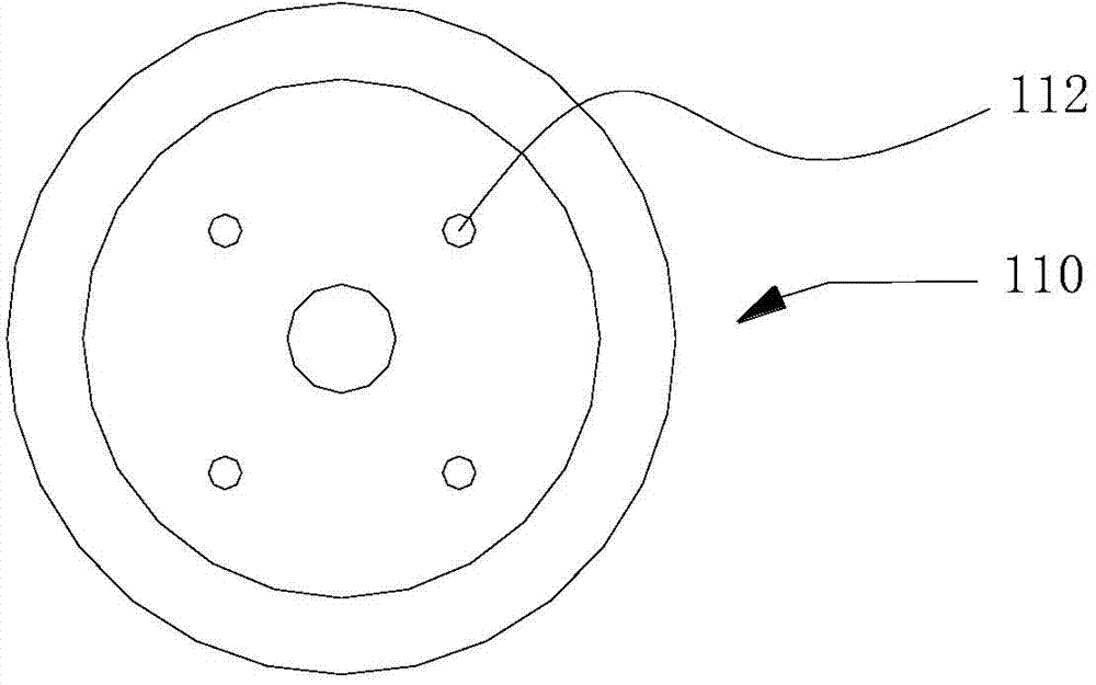
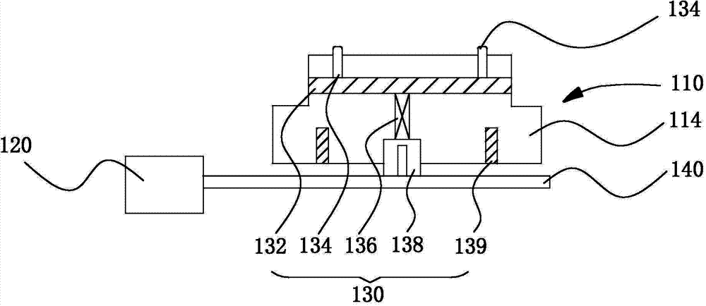
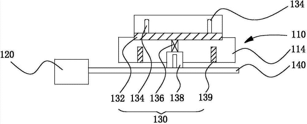
The invention discloses a baseplate conveying device. The baseplate conveying device comprises a vacuum sucker, a vacuum device and a vacuum breaker. An accommodating cavity is formed in the vacuum sucker; a through hole is formed in the top of the vacuum sucker; the vacuum device is communicated with the accommodating cavity of the vacuum sucker through a vacuum pipe, and is formed to a vacuum channel with the through hole; the vacuum breaker is accommodated and mounted in the accommodating cavity, and comprises a magnetic moving plate, an elastic device and an electromagnetic device; a thimble fitting the through hole is arranged at one side, aligned to the top of the vacuum sucker, of the magnetic moving plate; the electromagnetic device is mounted at the bottom of the vacuum sucker; and the magnetic moving plate is connected with the electromagnetic device through the elastic device. In the baseplate conveying device, when a baseplate is placed, the conveying beat of a mechanical arm and the vacuum release are synchronously performed without needing communication, so that the time is saved, the conveying beat of the mechanical arm is increased, and the production efficiency is improved. In addition, the vacuum is released without needing air blowing, so that the dry compressed air is saved, and the operational cost is reduced.

Description

technical field [0001] The invention relates to the field of flat panel display technology, in particular to a substrate conveying device. Background technique [0002] At present, in the flat display panel manufacturing industry, glass substrates are conveyed by rollers driven by rollers. However, this transmission method may cause damage to the internal structure of the glass substrate during the transmission process. After the glass substrate passes through multiple sets of rollers, the damage to the internal structure of the glass substrate will expand, which may cause the glass substrate to break in the subsequent coating and other processes. [0003] In order to increase the transfer rate to meet the production requirements and reduce the damage to the product during the transfer process, there is also a robot transfer, which uses vacuum technology to adsorb the substrate on the robot arm for transfer. In order to improve production efficiency and reduce the chance o...

Claims


Application Information

Patent Timeline
IPC IPC(8): B65G49/06
Inventor 裴绪章
Owner CHENGDU VISTAR OPTEOLECTRONICS CO LTD
Why Eureka
Try Eureka