A compressor oil separator

A compressor oil and separator technology, used in machines/engines, mechanical equipment, liquid fuel engines, etc., can solve the problems of excessive lubricating oil, the separation effect of oil and gas does not reach the desired effect, etc., and increase the centrifugal separation rate. , The effect of enhancing oil separation efficiency and increasing the effective number of rotations

Inactive Publication Date: 2015-07-01
SANDEN HUAYU AUTOMOTIVE AIR CONDITIONING CO LTD
View PDF10 Cites 3 Cited by
  • Summary
  • Abstract
  • Description
  • Claims
  • Application Information

AI Technical Summary

Problems solved by technology

[0004] In the prior art, there is a cylinder-shaped oil separation chamber. Although the structure is simple, the separation effect of oil and gas has not achieved the desired effect, and the discharged gas is still mixed with too much lubricating oil. oil separator for separating oil from gas

Method used


Image

  • A compressor oil separator
  • A compressor oil separator
  • A compressor oil separator

Examples


Embodiment Construction

[0018] The present invention will be further described below in conjunction with specific embodiment and accompanying drawing, set forth more details in the following description so as to fully understand the present invention, but the present invention can obviously be implemented in many other ways different from this description, Those skilled in the art can make similar promotions and deductions based on actual application situations without violating the connotation of the present invention, so the content of this specific embodiment should not limit the protection scope of the present invention.

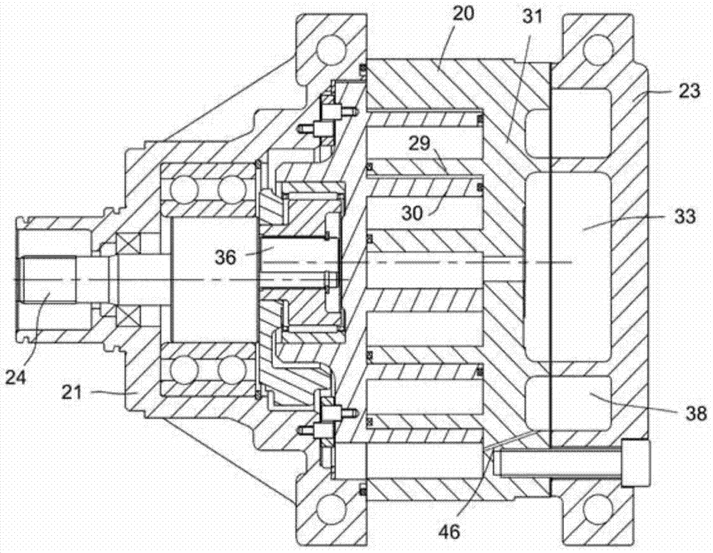
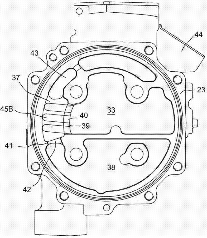
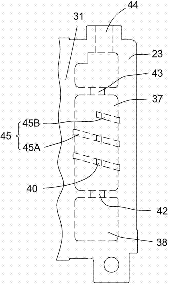
[0019] figure 1 A schematic diagram of a compressor in one embodiment of the invention is shown, which is a scroll compressor, but the invention is not limited thereto and may be other types of compressors. Figure 2 to Figure 3 The construction of the oil separator is shown. figure 2 Roughly correspond figure 1 Longitudinal sectional view of the middle and rear cylinder hea...


PUM

PropertyMeasurementUnit
Helix angleaaaaaaaaaa

Abstract

The technical problem to be solved by the invention is to provide a compressor oil separator to fully separate oil and gas. To overcome the technical problem, the compressor oil separator is provided and comprises an oil separating chamber and an oil storing chamber. The oil separating chamber is provided with connecting holes used for communicating with a gas discharging chamber of a compressor, is provided with an oil discharging hole communicated with the oil storing chamber, and is provided with a gas discharging path used for communicating a discharging port of the compressor. The compressor oil separator is characterized in that a spiral stream guiding groove is formed in the inner wall of the oil separating chamber.

Description

technical field [0001] The present invention relates to compressor oil separators. Background technique [0002] Chinese published patent document CN101517239A provides an oil separator structure of a scroll compressor, in which a curved cylindrical oil separation chamber is formed by docking a static scroll and a housing; the oil separation chamber communicates with the discharge chamber through a communication hole, and the oil separation chamber A lower hole is provided at the lower end of the separation chamber, so that the oil separation chamber communicates with the lower oil storage chamber, and the separated oil can flow back to the oil storage chamber under the action of gravity; a gas passage is provided at the upper end of the oil separation chamber, through which the separated gas will flow to the oil storage chamber. Exhaust. [0003] The oil-containing gas in the exhaust chamber enters the oil separation chamber 6 through the communication hole 7, and uses the...

Claims


Application Information

Patent Timeline
IPC IPC(8): F04C29/02
CPCF04C29/026
Inventor 杨瑞房锦忠邵雪峰
Owner SANDEN HUAYU AUTOMOTIVE AIR CONDITIONING CO LTD
Why Eureka
Try Eureka