A floating ball valve

A floating ball valve and valve body technology, applied in the field of valve manufacturing, can solve the problem that the floating ball valve cannot take into account the installation stability of the valve stem and the overall sealing performance of the ball valve, and achieve the effects of preventing leakage, ensuring stability and ensuring sealing stability.

Active Publication Date: 2018-09-21
NEWAY VALVE SUZHOU
View PDF6 Cites 0 Cited by
  • Summary
  • Abstract
  • Description
  • Claims
  • Application Information

AI Technical Summary

Problems solved by technology

[0007] Therefore, the technical problem to be solved by the present invention is to overcome the technical problem that the floating ball valve in the prior art cannot take into account the installation stability of the valve stem and the overall sealing performance of the ball valve, so as to provide a method for improving the installation stability of the valve stem and the overall sealing performance of the ball valve. , which in turn can adapt to higher pressure floating ball valves

Method used


Image

  • A floating ball valve
  • A floating ball valve
  • A floating ball valve

Examples


Embodiment 1

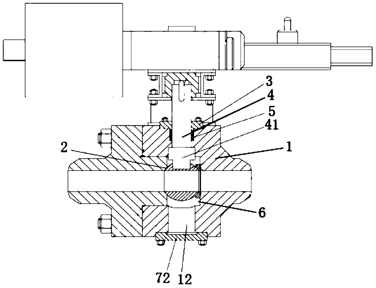
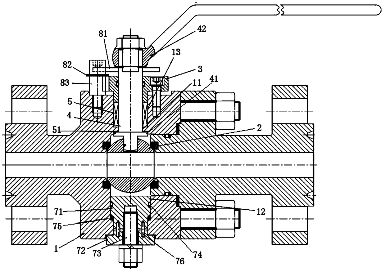
[0037] This embodiment provides a floating ball valve, including: a valve body 1, a valve core 2 arranged in the valve body 1, a valve stem installation hole 11 arranged on the valve body 1, a cover mounted on the valve stem The upper cover plate 3 on the installation hole 11 passes through the upper cover plate 3 and the valve stem installation hole 11 and extends into the valve body 1 and the valve stem 4 which is set in conjunction with the valve core 2 , the valve stem 4 and the valve body 1 are sealed and connected through the sealing packing 5, the bottom of the valve body 1 is provided with a through hole 12 opposite to the valve stem installation hole 11, and the through hole 12 is sealed. A sealing assembly for the hole 12, the through hole 12 has a first through hole portion 121 and a second through hole portion 122 connected to the first through hole portion 121 and having an inner diameter smaller than the first through hole portion 121, the sealing assembly It inc...

Embodiment 2

[0063] This embodiment provides a floating ball valve, which is a deformation on the basis of Embodiment 1. It differs from Embodiment 1 only in the setting of the fixing structure, such as Image 6 As shown, in the fixing structure of this embodiment, the stud 73 is directly formed on the end of the valve plug 71 close to the lower cover plate 72 (that is, the end of the valve plug 71 close to the lower cover plate 72 has a columnar protrusion, and the protrusion The outer surface of the raised portion is formed with threads, so that the raised portion becomes a stud 73), and the arrangement of the nut 77 and the lower cover plate 72 is the same as in Embodiment 1. The stud 73 is directly molded on the valve plug 71 to make installation and disassembly more convenient.

Embodiment 3

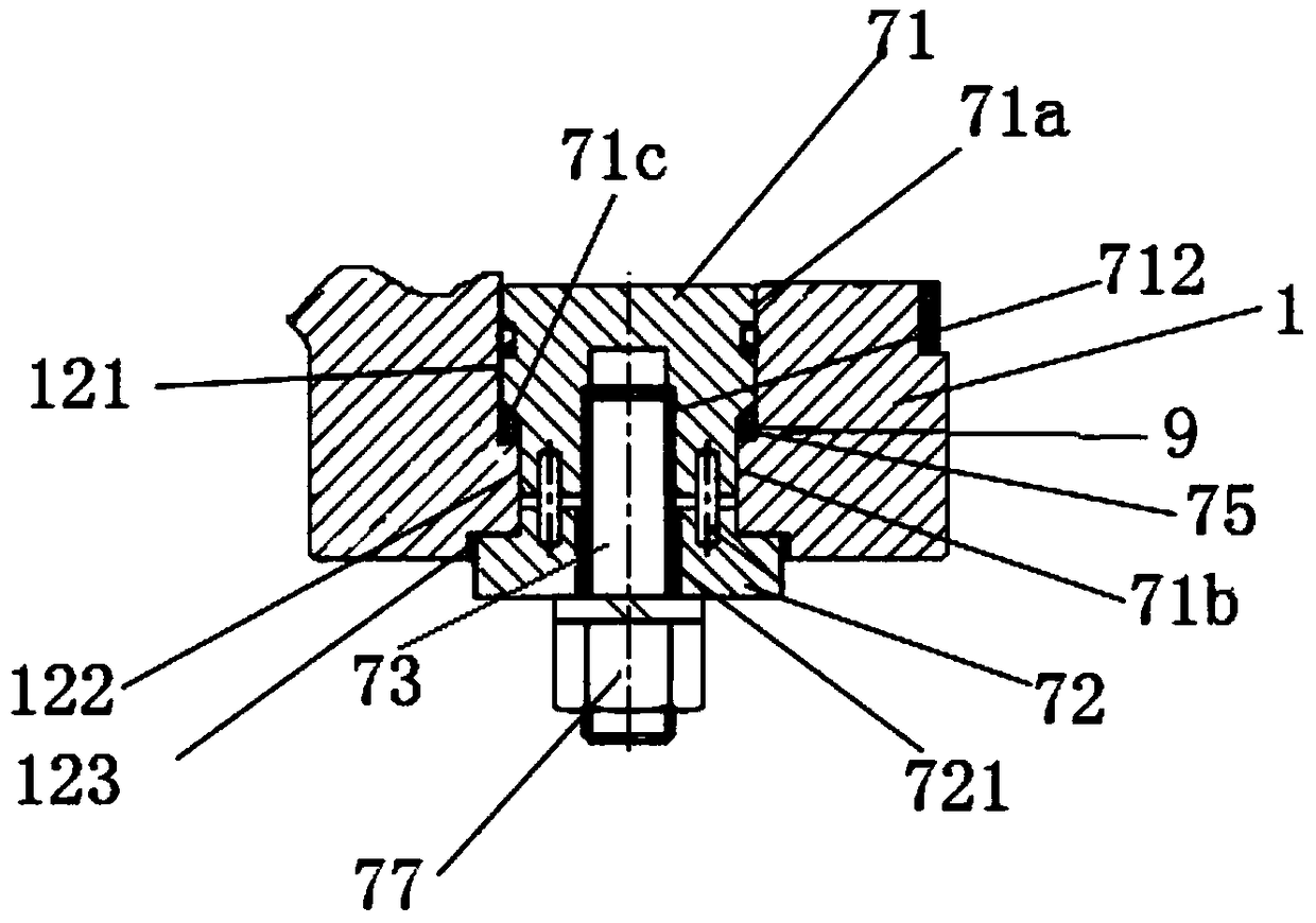
[0065] This embodiment provides a floating ball valve, which is a deformation on the basis of Embodiment 1. It differs from Embodiment 1 only in the setting of the fixing structure, such as Figure 7 As shown, the fixing structure of this embodiment includes four screw holes 712 symmetrically formed on the valve plug 71 , and similarly, the number of mounting holes 721 and nuts 77 is also four. Certainly, other numbers of the screw holes 712, the installation holes 721 and the nuts 77 may also be used. After a plurality of screw holes 712 , installation holes 721 and nuts 77 are provided, the connection between the valve plug 71 and the lower cover plate 72 is more stable.


PUM


Abstract

The invention provides a floating ball valve. A through hole is formed in the bottom of the valve body, so that a valve rod smaller than the inner diameter of the through hole is installed in a valve rod installation hole through the through hole and a cavity, and lower mounting of the valve rod and blowing-out prevention are achieved. In addition, the through hole is set to be of a structure with a first through hole portion and a second through hole portion of which the inner diameter is smaller than that of the first through hole portion, a valve plug can not be blown out of the bottom of a valve body under the action of high-pressure media through the function of a protrusion of the second through hole portion, and after the valve plug is connected with a lower cover board, upward movement of the valve plug is blocked by a valve deck, so that after the valve plug and the lower cover board are connected, upward and downward movement of a whole sealing assembly is limited. Meanwhile, the valve plug is in sealed fit with the inner wall of the first through hole portion and / or the second through hole portion, the high-pressure media are prevented from being leaked from the gap between the through hole and the valve plug, the sealing performance of the ball valve is improved, and the ball valve can adapt to media of higher pressure.

Description

technical field [0001] The invention relates to a floating ball valve, which belongs to the field of valve manufacturing. Background technique [0002] Floating ball valve is a kind of ball valve whose spool can move under the action of medium. Under the action of medium pressure, the spool can produce a certain displacement and press tightly on the sealing surface of the outlet end to seal the outlet end. In order to realize the control of the floating ball valve, the valve stem needs to pass through the valve stem mounting hole on the valve body to be set in linkage with the valve core, and the rotation of the valve core is controlled by rotating the valve stem to realize the opening and closing of the valve. In order to allow the floating ball valve to be used under high-pressure medium, a structure with a small inner cavity, a small valve core, and a thick valve wall (thickness of the valve body and the upper cover plate) is often used, and a valve stem of sufficient len...

Claims


Application Information

Patent Timeline
Patent Type & Authority Patents(China)
IPC IPC(8): F16K5/08F16K27/06F16K5/06
CPCF16K5/0663F16K5/08F16K27/067
Inventor 陈尚东王文广韩金忠
Owner NEWAY VALVE SUZHOU
Why Eureka
Try Eureka