Optical auxiliary measuring device and measuring method using the device

An auxiliary device and measurement technology, which is used in measurement devices, optical instrument testing, and machine/structural component testing. It can solve the problems of measurement error and low repeatability, and achieve high repeatability and stable measurement. good effect

Inactive Publication Date: 2018-09-21
GENIUS ELECTRONICS OPTICAL XIAMEN
View PDF5 Cites 0 Cited by
  • Summary
  • Abstract
  • Description
  • Claims
  • Application Information

AI Technical Summary

Problems solved by technology

[0004] In summary, since the optical lens 9 and the tray 8 are respectively placed on the tray 8 and the measurement platform (not shown) by their own weight, it is easy to cause measurement errors due to unstable placement positions, so the measurement The repeatability of the measurement is not high

Method used


Image

  • Optical auxiliary measuring device and measuring method using the device
  • Optical auxiliary measuring device and measuring method using the device
  • Optical auxiliary measuring device and measuring method using the device

Examples


Embodiment Construction

[0046] Before elaborating the present invention in detail, it should be noted that in the following description, similar elements are denoted by the same numerals.

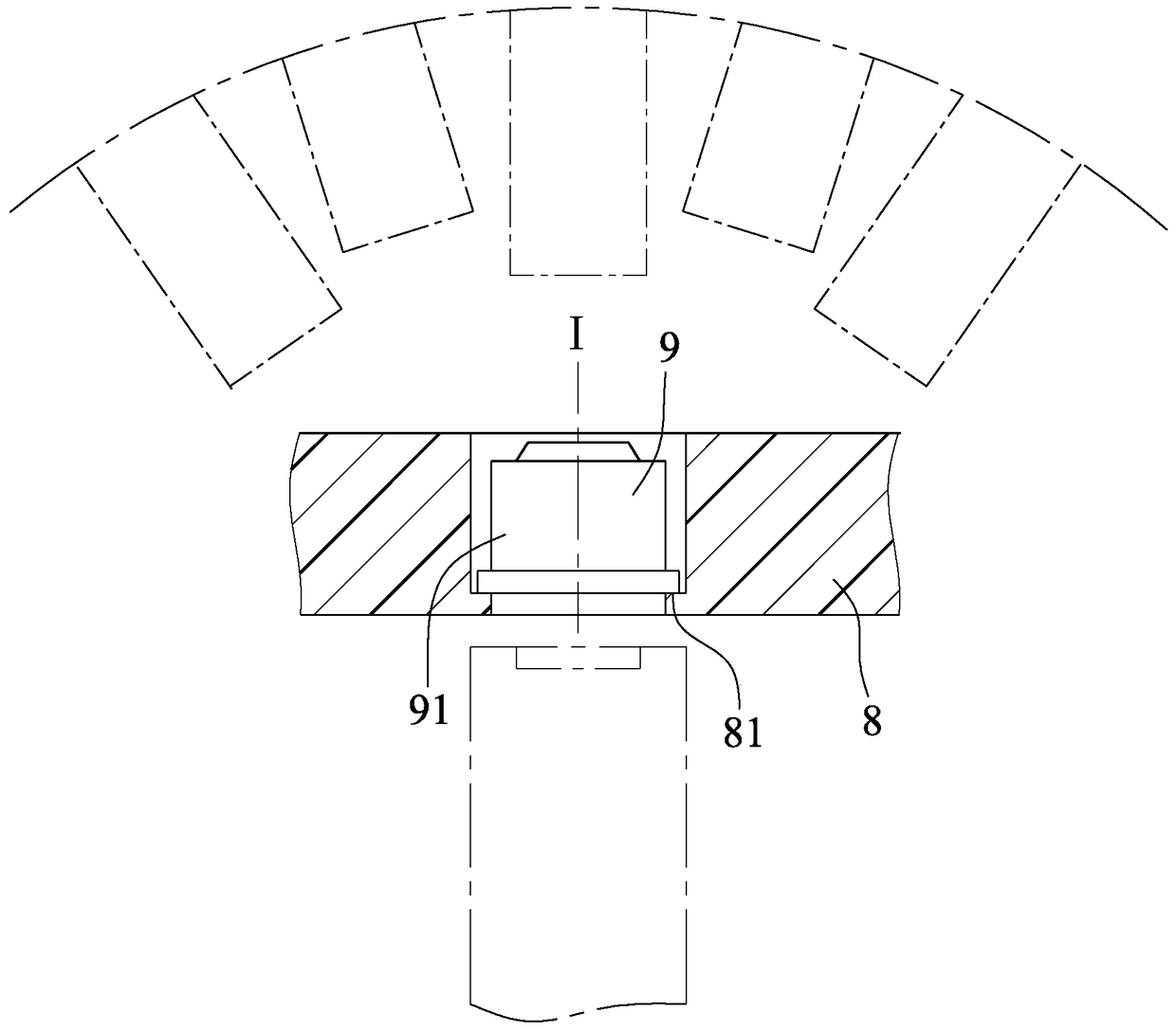
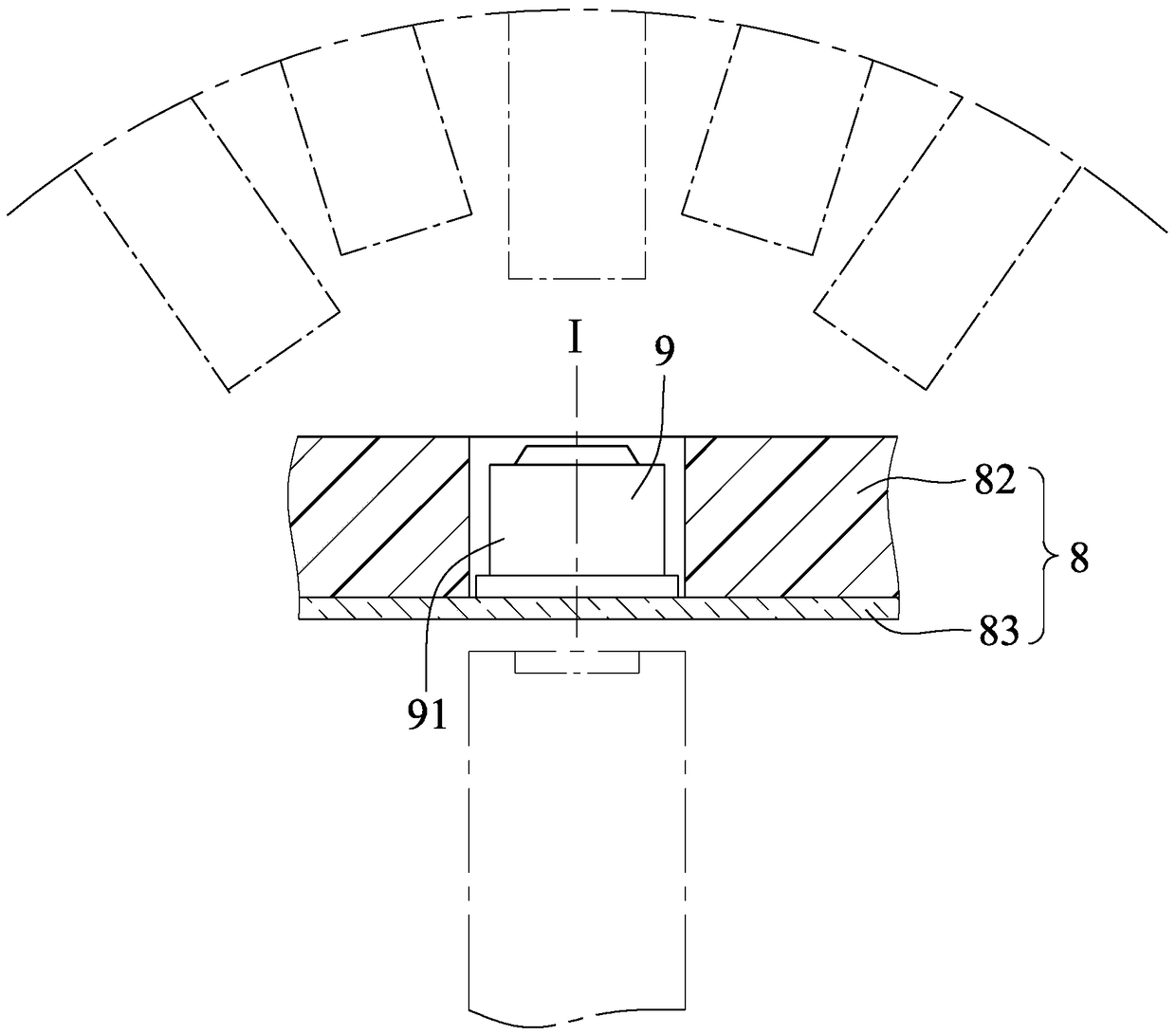
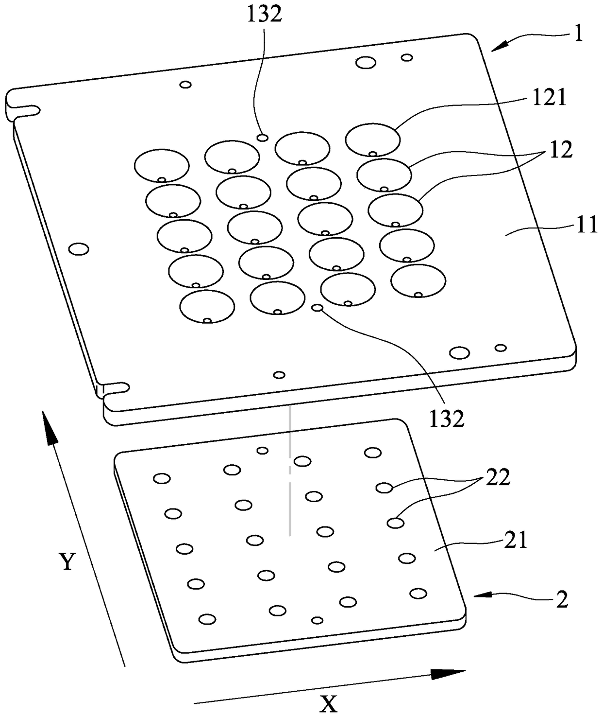
[0047] refer to image 3 , Figure 4 and Figure 5 , a first preferred embodiment of the optical measurement auxiliary device of the present invention is used for optical measurement of a plurality of objects to be measured 90. In this embodiment, the object to be measured 90 is an optical lens, and the optical measurement auxiliary The device includes: a suction unit 1 and a bearing unit 2 .

[0048] The pick-up unit 1 is used to pick up the object to be tested 90, and includes a body 11, a plurality of volumes that are spaced through the body 11 along a first direction X and a second direction Y perpendicular to the first direction X respectively. Measuring hole 12, and a gas channel 13 arranged in the body 11. The measuring holes 12 respectively have a first port 121 and a second port 122 formed on the surf...


PUM


Abstract

The invention relates to an optical auxiliary measuring device comprising a suction unit and a carrying unit. The suction unit includes a main body, at least one measuring hole through the main body, and a gas flow channel arranged in the main body. The measuring hole has a first port and a second port formed on the surface of the body and oppositely arranged. The gas channel has at least one suction port formed on the surface of the body near the second port, and at least one suction port formed on the surface of the body. A contact surface is formed on the body surface close to the suction opening. The carrying unit includes a base plate and at least one placement groove formed by a downward depression of the top surface of the base plate, and the placement slot can be used for placing the object to be tested. The measurement method using the device includes a preparation step, a suction step, a measurement step and a detachment step.

Description

technical field [0001] The invention relates to a measurement of an optical element, in particular to an optical auxiliary measurement device and a measurement method using the device. Background technique [0002] refer to figure 1 , the traditional optical lens 9 is assembled and placed in the tray 8, and then the optical characteristics are measured. Because the optical lens at the rear end of the lens barrel 91 of the optical lens 9 is usually larger, the wall of the lens barrel 91 is very thin, and the optical lens 9 is placed on the abutment surface 81 of the tray 8 through the rear end of the lens barrel 91. Therefore, the precision of the abutment surface 81 of the tray 8 must be very high to ensure that the axis I is perpendicular to the extending direction of the tray 8 when the optical lens 9 is placed. [0003] refer to figure 2 , another kind of tray 8 is combined with plastic tray 82 and glass 83, glass 83 can transmit light and the flatness of glass 83 sur...

Claims


Application Information

Patent Timeline
Patent Type & Authority Patents(China)
IPC IPC(8): G01M11/00
Inventor 叶瀚楯董建成
Owner GENIUS ELECTRONICS OPTICAL XIAMEN
Why Eureka
Try Eureka