
Rotor, induction motor having the same, and method for manufacturing the same

A manufacturing method and rotor technology, which is applied in the manufacture of the assembly structure of the rotor rod and end ring, the assembly structure of the rotor rod and end ring, and the field of induction engines, which can solve the problem of fragile joints and high-heat rotor rod and end ring materials Reduced strength and other issues, to achieve the effect of reducing the number of assembly processes

Active Publication Date: 2015-07-01
HYUNDAI MOBIS CO LTD
View PDF8 Cites 2 Cited by
  • Summary
  • Abstract
  • Description
  • Claims
  • Application Information

AI Technical Summary

Problems solved by technology

[0018] The present invention is proposed in order to solve the problems of the above-mentioned background technology, and the purpose of providing a rotor, an induction motor suitable for the rotor, and a manufacturing method thereof is to solve the problem that the strength of the rotor rod and the end ring material decreases due to high heat during welding
[0019] In addition, another object of the present invention to provide a rotor, an induction motor applicable to the rotor and a manufacturing method thereof is to solve the problem that stress concentration occurs at the welded part during welding and causes the joint part to be fragile.

Method used


Image

  • Rotor, induction motor having the same, and method for manufacturing the same
  • Rotor, induction motor having the same, and method for manufacturing the same
  • Rotor, induction motor having the same, and method for manufacturing the same

Examples


Embodiment Construction

[0052] The present invention can be modified variously and has various embodiments, and specific embodiments are illustrated in the drawings and described in detail in the detailed description. However, this is not intended to limit the present invention with respect to the specific embodiments, but should be interpreted as including all changes, equivalents, and substitutions included in the technical idea and technical scope of the present invention.

[0053] Similar reference signs are used for similar constituent elements while describing the respective drawings.

[0054] The terms 1st, 2nd, etc. may be used to describe various constituent elements, but the constituent elements shall not be limited by the terms, and the terminology is used only for the purpose of distinguishing one constituent element from other constituent elements.

[0055] For example, a first constituent element may be named a second constituent element, and a similar second constituent element may als...


PUM


Abstract

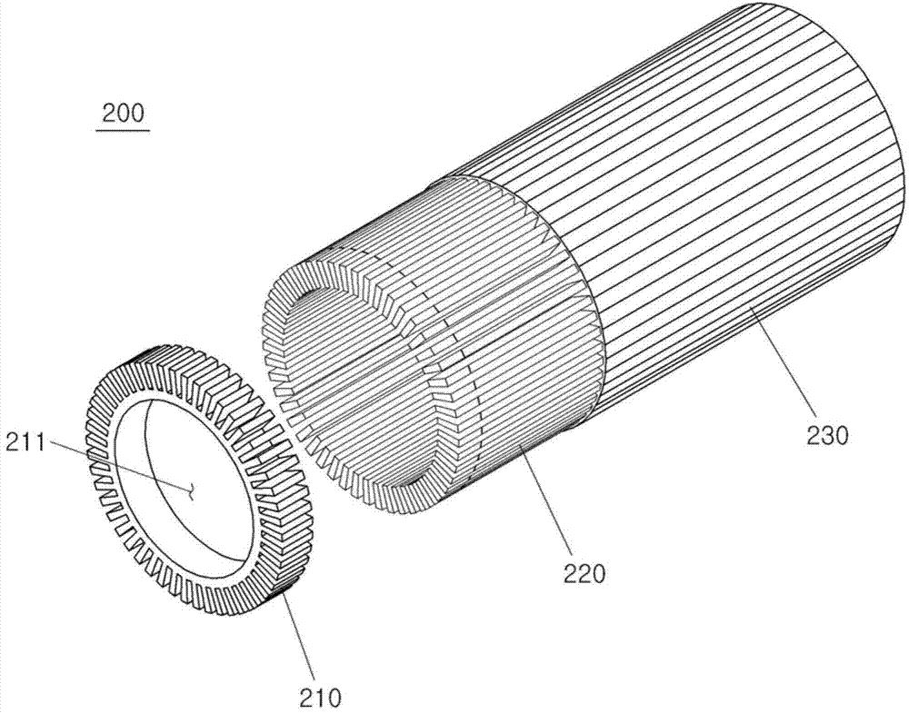
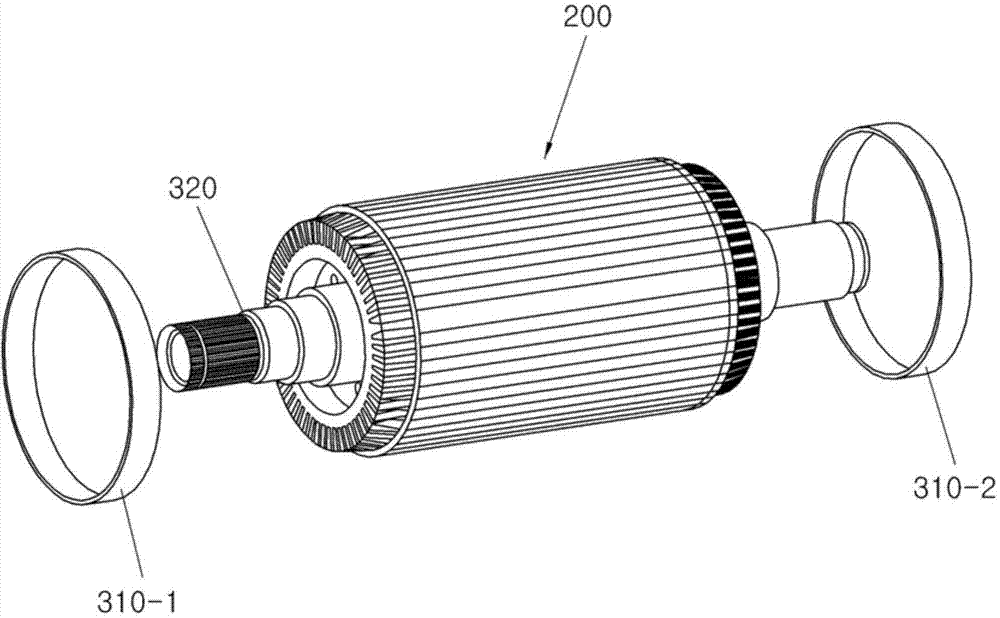
A rotor includes a stacked core having a plurality of slots formed on an inner side thereof, a plurality of rotor bars inserted in the plurality of slots, a pair of end rings assembled and fastened to opposite ends of the rotor bars, a pair of retainers fastened to opposite outer end surfaces of the rotor bars in an assembled and fastened manner, and a shaft inserted into the pair of end rings.

Description

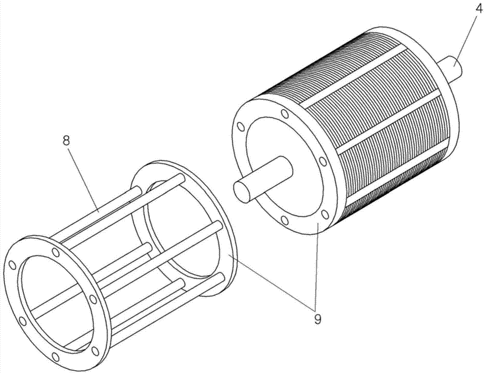
technical field [0001] This invention relates to rotors and, more particularly, to the assembly of rotor rods and end rings for induction motors. [0002] In addition, the present invention relates to an induction motor to which such a rotor rod and end ring assembly structure is applied. [0003] In addition, the present invention relates to a method of manufacturing such a rotor rod and end ring assembly. Background technique [0004] The rotor of the induction motor is composed of electrical steel plates, rotor rods and end rings. Generally speaking, a copper rotor rod is used. In this case, the copper rotor rod matching the shape of the electrical steel plate is made and inserted into the electrical steel plate, and the upper / lower copper rotor rod and the end ring are connected by welding. [0005] It is easiest to make the end ring shape into a ring shape to connect with the copper rotor rod, which is shown in figure 1 , refer to figure 1 It is composed of a stator...

Claims


Application Information

Patent Timeline
Patent Type & Authority Applications(China)
IPC IPC(8): H02K1/22H02K15/02
CPCH02K3/02H02K15/09H02K3/12H02K15/0012H02K17/165H02K15/063H02K1/30Y10T29/49012H02K17/20H02K15/02H02K1/28
Inventor 金尚真
Owner HYUNDAI MOBIS CO LTD
Learn More