Pressure detection safety device
A safety device and pressure technology, which can be used in container discharge methods, container filling methods, gas/liquid distribution and storage, etc., and can solve the problems of many assembly processes, poor operability, and large number of parts.
- Summary
- Abstract
- Description
- Claims
- Application Information
AI Technical Summary
Problems solved by technology
Method used
Image
Examples
Embodiment 1
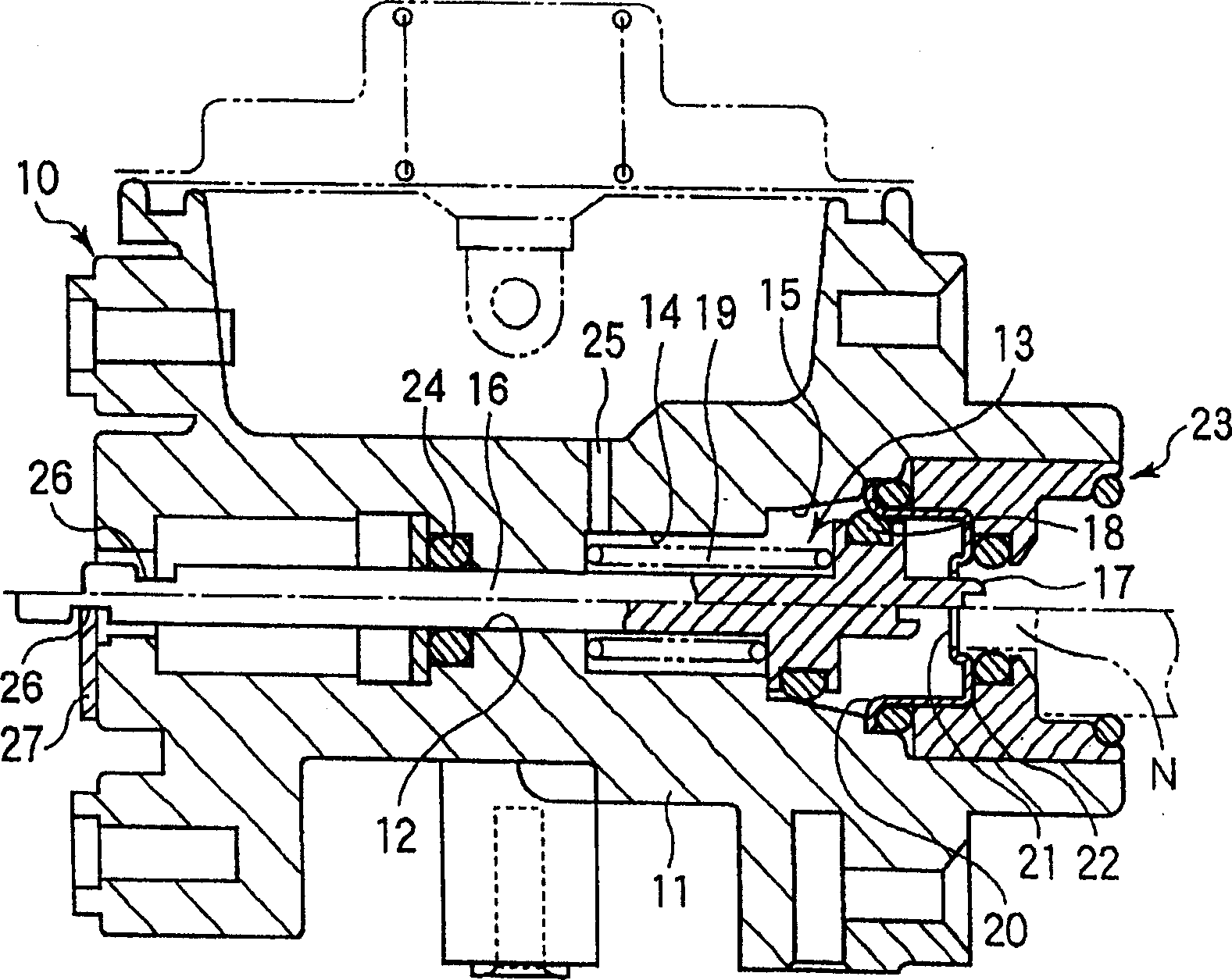
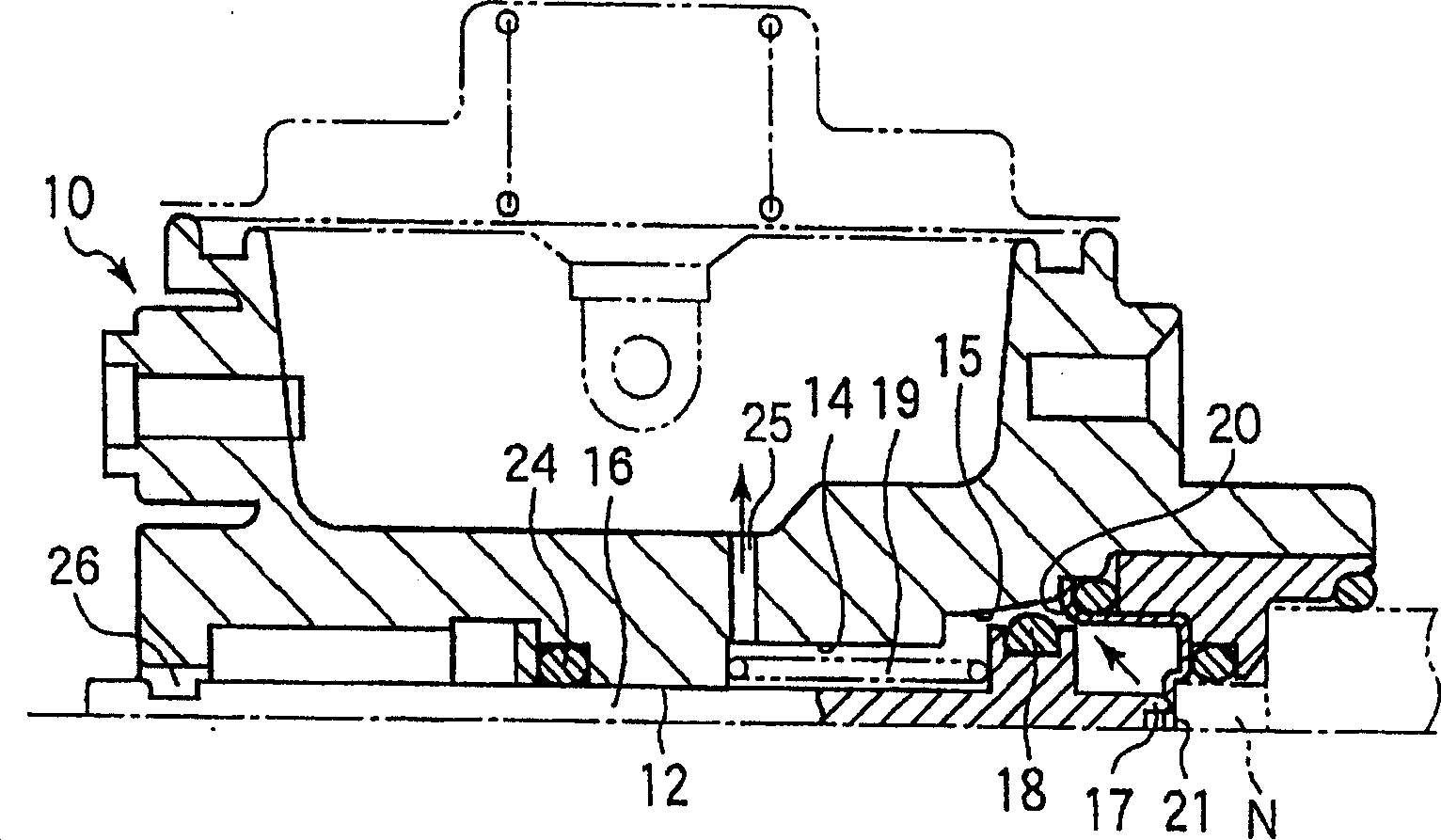
[0057] figure 1 , 2 shows a cross-sectional view of a pressure reducer 10 equipped with a pressure detection safety device according to Embodiment 1 of the present invention, that is, a so-called gas pressure regulator. The device body 11 of the present invention is attached with the above-mentioned pressure reducer 10 and is integrally formed therewith. A through hole 12 is formed on the main body 11, and an operation chamber 13 with a gas communication port 25 communicating with the decompression chamber is provided on the front half thereof. In addition, the plunger 16 penetrates from the front end to the rear end of the through hole. In this example, a spring receiving portion 14 is provided at the innermost portion of the operating chamber 13 , and a compression spring 19 provided there exerts a forward force on the plunger 16 .
[0058] The plunger 16 is a shaft-shaped member slidably arranged in the through hole 12 in the axial direction, and extends from one end of ...
Embodiment 2
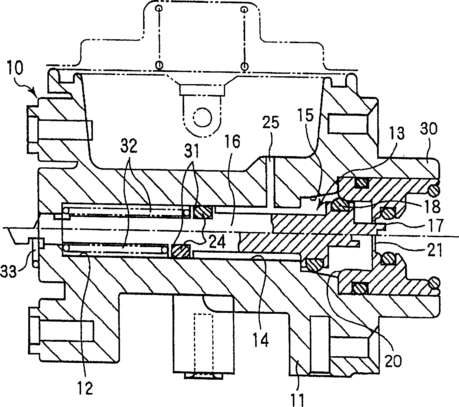
[0070] image 3 It is the same view as that of Embodiment 1, showing the pressure reducer 10 equipped with the pressure detection safety device of Embodiment 2 of the present invention. In Embodiment 2, a circumferential receiving groove 31 is provided in the middle of the plunger 16, and an inner sealing member 24 is installed, and a compression spring 32 exerts forward elastic force on the plunger from the rear of its outer wall. In this structure, the outer wall of the receiving groove 31 also serves as a pressure-receiving portion on the side of the operating chamber, and it becomes easier to detect the abnormal pressure of the small gas tank as compared with the first embodiment.
[0071] In addition, in the second embodiment, the covering member 22 and the interface member 23 shown in the first embodiment are integrated to form a single head member 30 . Therefore, the outer seat portion 20 is formed on the above-mentioned head member. Thereby, while having the same bas...
Embodiment 3
[0074] Figure 4It is the same view as that of Embodiment 1, showing the pressure reducer 10 equipped with the pressure detection safety device of Embodiment 3 of the present invention. In Embodiment 3, as in Embodiment 1, a compression spring 19 is provided in the operating chamber 13, but a spring receiving portion 141 is also provided behind the sealing member 24 in the through hole that makes the plunger 16 slide. The compression spring 191 of the receiving portion pushes the plunger 16 forward. That is, in figure 1 In the first embodiment shown, the functions of the compression spring 19 are divided into the compression spring 19 for the one-way valve and the compression spring 191 for the shut-off valve. In this way, the one-way valve can be operated more smoothly. And other respects are identical with embodiment 1.
PUM
 Abstract
Description
Claims
Application Information
 - R&D
- Intellectual Property
- Life Sciences
- Materials
- Tech Scout
- Unparalleled Data Quality
- Higher Quality Content
- 60% Fewer Hallucinations
Browse by: Latest US Patents, China's latest patents, Technical Efficacy Thesaurus, Application Domain, Technology Topic, Popular Technical Reports.
© 2025 PatSnap. All rights reserved.Legal|Privacy policy|Modern Slavery Act Transparency Statement|Sitemap|About US| Contact US: help@patsnap.com


