Cambered surface type two-degree-of-freedom permanent magnet in-wheel motor

A technology of in-wheel motors and degrees of freedom, applied in motors, synchronous motors with stationary armatures and rotating magnets, electric vehicles, etc., can solve problems such as occupancy, large vehicle space, and increased vehicle unsprung mass

Inactive Publication Date: 2015-07-01
HARBIN INST OF TECH
View PDF3 Cites 16 Cited by
  • Summary
  • Abstract
  • Description
  • Claims
  • Application Information

AI Technical Summary

Problems solved by technology

[0003] However, traditional electric vehicles use multiple motors and mechanical transmission and steering systems to realize the functions of straight-line driving, steering and offset. The structure is complex and takes up a lot of vehicle space, which increases the unsprung mass of the vehicle, resulting in vehicle stability. and comfort is difficult to improve

Method used


Image

  • Cambered surface type two-degree-of-freedom permanent magnet in-wheel motor
  • Cambered surface type two-degree-of-freedom permanent magnet in-wheel motor
  • Cambered surface type two-degree-of-freedom permanent magnet in-wheel motor

Examples


specific Embodiment approach 1

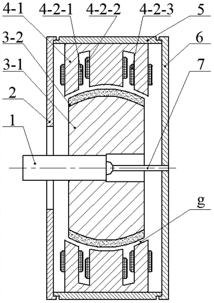
[0025] Specific implementation mode 1, refer to Figure 3 to Figure 9 Describe this embodiment in detail, the arc surface two-degree-of-freedom permanent magnet hub motor described in this embodiment includes a rotor, a stator, a shaft 1, a left end cover 2, a housing 5, a right end cover 6 and a bearing 7; the rotor includes a rotor iron Core 3-1 and permanent magnet 3-2, the stator includes stator iron core 4-1 and stator winding 4-2; stator winding 4-2 includes left yaw winding 4-2-1, drive winding 4-2-2 and Right swing winding 4-2-3;

[0026] The two end faces of the housing 5 are respectively provided with a left end cover 2 and a right end cover 6, the left end of the shaft 1 protrudes from the left end cover 2, and the right end of the shaft 1 is movably connected with the right end cover 6 through a bearing 7;

[0027] The rotor or stator is fixed on the shaft 1, and the inner wall of the housing 5 is correspondingly provided with a stator or rotor; and there is a uni...

specific Embodiment approach 2

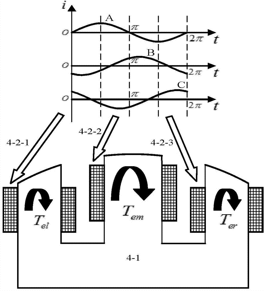
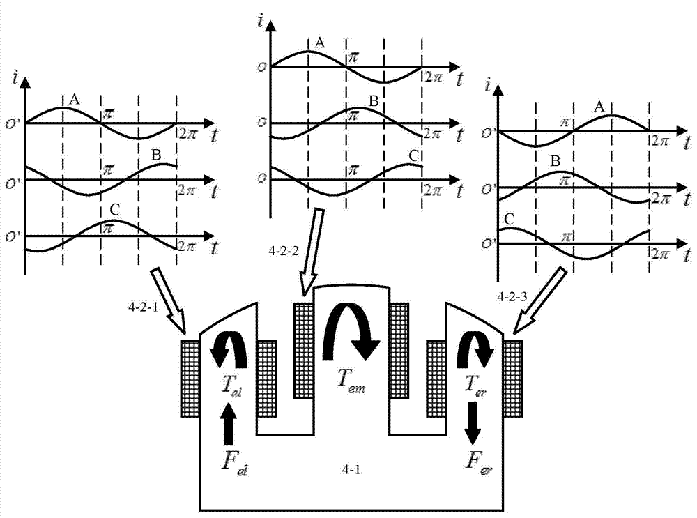
[0029] Specific embodiment 2. This specific embodiment is a further description of the arc surface two-degree-of-freedom permanent magnet hub motor described in specific embodiment 1. In this embodiment, the stator core 4-1 is divided into three parts along the axial direction. Each part is configured with an armature winding, wherein the middle part is configured with a drive winding 4-2-2, and the parts on both sides are respectively configured with a left yaw winding 4-2-1 and a right yaw winding 4-2-3.

specific Embodiment approach 3

[0030] Specific embodiment three. This specific embodiment is a further description of the arc surface two-degree-of-freedom permanent magnet hub motor described in specific embodiment two. In this embodiment, the left yaw winding 4-2-1, the drive winding 4- 2-2 and the right swing winding 4-2-3 have the same equivalent number of poles of the exciting magnetic field, and both are realized by adopting concentrated winding or distributed winding.


PUM


Abstract

The invention discloses a cambered surface type two-degree-of-freedom permanent magnet in-wheel motor and relates to the field of motors. The cambered surface type two-degree-of-freedom permanent magnet in-wheel motor has two degrees of freedom, including rotation and deflection, thereby integrating a driving function of an in-wheel motor and a steering function of a steering motor in an electric vehicle skillfully. A stator core of the permanent magnet in-wheel motor is divided into a plurality of portions effectively, each portion is provided with an armature winding in a specific arrangement mode, and a rotor is provided with a permanent magnet. Based on a magnetic field harmonic theory and a self-bearing magnetic levitation principle, rotation of the motor can be achieved by a driving winding in the middle of a stator, and deflection motion of the motor can be achieved by deflection windings on two sides of the stator. An even air gap is arranged between the stator core and the rotor, the lateral surface of the air gap of the stator core and the lateral surface of the air gap of the rotor are concentric spherical cambered surfaces, and during rotation and deflection motion of the rotor, the air gap at any position between the stator and the rotor is kept unchanged constantly. A bearing can be a spherical motor bearing and the like. The cambered surface type two-degree-of-freedom permanent magnet in-wheel motor is applicable to driving of the electric vehicle.

Description

technical field [0001] The invention relates to the field of electric motors, in particular to a novel structure multifunctional arc surface two-degree-of-freedom permanent magnet hub motor. Background technique [0002] Since the beginning of the 21st century, electric vehicles have gone through the stages from concept cars to promotion and popularization. In order to improve driving comfort and comfort, more and more mechanical parts are showing a trend of being replaced by electronic devices, using hub motors to drive Electric vehicles can improve vehicle handling and interior space. [0003] However, traditional electric vehicles use multiple motors and mechanical transmission and steering systems to realize the functions of straight-line driving, steering and offset. The structure is complex and takes up a lot of vehicle space, which increases the unsprung mass of the vehicle, resulting in vehicle stability. and comfort are difficult to improve. Therefore, the researc...

Claims


Application Information

Patent Timeline
Patent Type & Authority Applications(China)
IPC IPC(8): H02K21/14H02K1/27
CPCY02T10/64
Inventor 柴凤裴宇龙甘磊李义高立骁
Owner HARBIN INST OF TECH
Why Eureka
Try Eureka