
Focus control apparatus and method

一种对焦控制、摄像装置的技术,应用在电视、彩色电视的零部件、电视系统的零部件等方向,能够解决难焦点对准点光源等问题,达到提高合焦精度的效果

Inactive Publication Date: 2015-07-01
HITACHI INFORMATION & CONTROL SOLUTIONS LTD
View PDF5 Cites 13 Cited by
  • Summary
  • Abstract
  • Description
  • Claims
  • Application Information

AI Technical Summary

Problems solved by technology

[0004] However, in the focusing method of the autofocus function, it is often difficult to focus on a point light source in a dark place

Method used


Image

  • Focus control apparatus and method
  • Focus control apparatus and method
  • Focus control apparatus and method

Examples


Embodiment Construction

[0023] An embodiment of the present invention will be described in detail below with reference to the drawings.

[0024] (1) Configuration of the imaging device 1

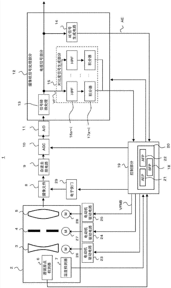
[0025] figure 1 It is a block diagram showing the overall configuration of the imaging device 1 according to this embodiment.

[0026] The lens unit 2 of the imaging device 1 includes a zoom lens group 3 for zooming in and out of a light beam from a subject, an aperture 4 for adjusting the amount of received light, and a focus lens group 5 having a focus adjustment function.

[0027] The lens unit 2 is provided with, for example, a lens origin detector 6 and a temperature detector 7 composed of a photointerrupter or the like. The lens origin detector 6 detects the absolute positions of the zoom lens group 3 and the focus lens group 5, and sends the detection results to the control section 19 as lens absolute position information. The temperature detector 7 detects the temperature inside the lens unit 2 and sends...


PUM


Abstract

A focus control apparatus that achieves a focused state even when a subject is a point light source includes a contrast signal generator that divides a captured image screen into a plurality of areas, extracts a frequency component based on a video signal for each of the divided areas, and generates a first contrast signal based on the frequency component. A controller extracts a luminance intensity based on the video signal for each of the divided areas, determines, for each of the divided areas, a second contrast signal generated by increasing or decreasing the magnitude of the first contrast signal from the divided area based on the magnitude of the luminance intensity, determines a lens position evaluation value that is the sum of the second contrast signals, and performs the focus control based on the lens position evaluation value.

Description

technical field [0001] The invention relates to a focus control device and method. Background technique [0002] Conventionally, many imaging devices, such as surveillance cameras and DVD (Digital Versatile Disc) cameras, are equipped with an autofocus function for automatically adjusting the focus. As a focusing method in the above-mentioned autofocus function, there is known a contrast method, which adjusts the focus using the principle that the position where the amplitude of the contrast signal of the captured image becomes the maximum value is in the in-focus state. [0003] In an imaging device, as the focus lens moves along its optical axis, the captured image becomes defocused or in-focus, and the amplitude of the contrast signal also changes accordingly. In the most basic contrast method, the focus lens is first moved along its optical axis, and then the focus direction is detected based on the amplitude of the contrast signal before and after the movement, and the...

Claims


Application Information

Patent Timeline
Patent Type & Authority Applications(China)
IPC IPC(8): H04N5/232
CPCH04N5/23212H04N23/673
Inventor 梅泽伊织西口友明
Owner HITACHI INFORMATION & CONTROL SOLUTIONS LTD
Features
  • Generate Ideas
  • Intellectual Property
  • Life Sciences
  • Materials
  • Tech Scout
  • Unparalleled Data Quality
  • Higher Quality Content
  • 60% Fewer Hallucinations
Learn More