Gear box centering based laser centering tool of ship shaft system and centering mounting method

A technology of laser centering and gear boxes, which is applied in shipbuilding, ship design, tool manufacturing, etc. It can solve the problems of insufficient installation accuracy and limited application range, and achieve the effects of high installation accuracy, wide application range and high precision

Active Publication Date: 2015-07-08
CSSC HUANGPU WENCHONG SHIPBUILDING COMPANY
View PDF6 Cites 14 Cited by
  • Summary
  • Abstract
  • Description
  • Claims
  • Application Information

AI Technical Summary

Benefits of technology

This new technology proposes an improved way to align with gears used inside ships during construction or maintenance work. It uses lasers instead of traditional methods like wires drawings, resulting in more accurate results compared to previous techniques such as wire drawn ones. Additionally, this technique allows for wide-ranging applications even if there aren’t any holes around them due to their shape.

Problems solved by technology

The technical problem addressed in this patented solution involves improving the efficiency and precision of aligning and installing ships' shipping equipment without causing excessive wear or damage caused by the weight force from the steel wires used during the process.

Method used


Image

  • Gear box centering based laser centering tool of ship shaft system and centering mounting method
  • Gear box centering based laser centering tool of ship shaft system and centering mounting method
  • Gear box centering based laser centering tool of ship shaft system and centering mounting method

Examples


Embodiment Construction

[0037] In order to facilitate the understanding of those skilled in the art, the present invention will be further described below in conjunction with the accompanying drawings and embodiments.

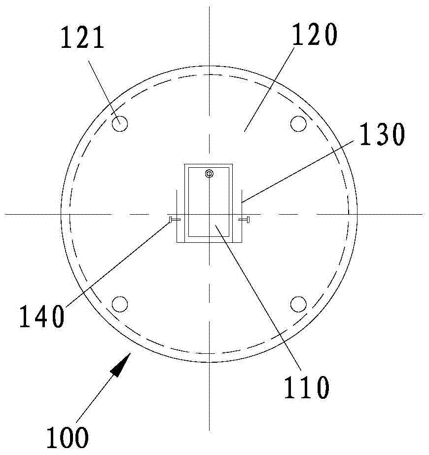
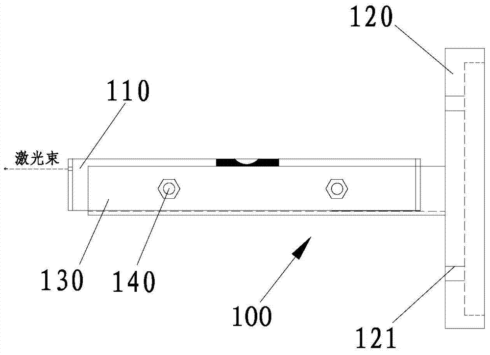
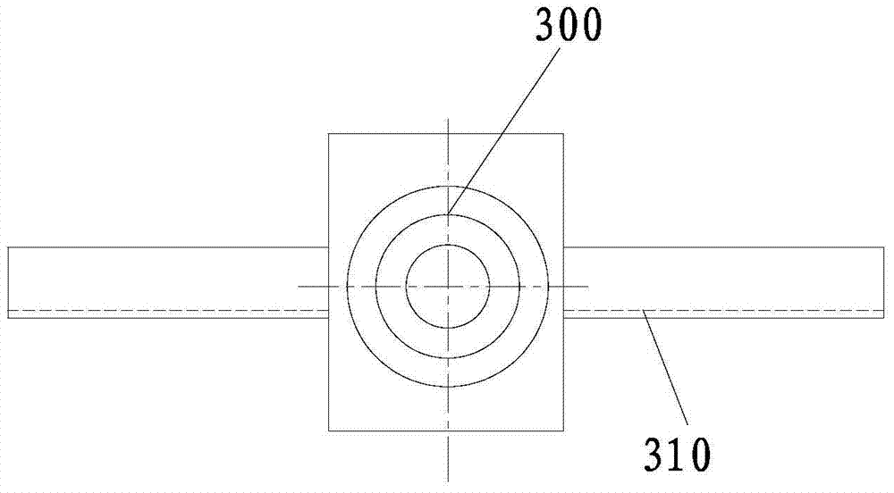
[0038] Please also refer to Figure 1 to Figure 4 , figure 1 It is a schematic diagram of the front view structure of the laser device in the embodiment of the ship shafting laser centering tool based on the gear box centering proposed by the present invention, figure 2 yes figure 1 The right-view structure diagram of image 3 It is a schematic diagram of the front view structure of the laser target in the embodiment of the gear box centering-based ship shafting laser centering tool proposed by the present invention, Figure 4 It is a schematic diagram of centering installation of an embodiment of a ship shafting laser centering tool based on gear box centering proposed by the present invention.

[0039] An embodiment of a ship shafting laser alignment tool based on gear box alig...


PUM


Abstract

The invention relates to a gear box centering based laser centering tool of a ship shaft system and a centering mounting method. The tool comprises a laser device; the laser device comprises a laser, a blind board flange plate, a fixing bracket and a calibration part, wherein the blind board flange plate is bolted to a horizontal transmission flange of the gear box of the ship shaft system and is adapted to the horizontal transmission flange; one end of the fixing bracket is fixed on the first surface of the blind board flange plate; the laser is mounted on the fixing bracket through the collection part; the calibration part can be adjusted to adjust the fixing state of the laser so that a light path of the laser can be aligned to the center of the horizontal transmission flange. The tool has the advantages of being high in centering mounting precision and wide in applicable scope.

Description


Claims


Application Information

Patent Timeline
Owner CSSC HUANGPU WENCHONG SHIPBUILDING COMPANY
Why Eureka
Try Eureka