Ball clamping sliding device and ball clamping sliding door and window

A technology of sliding device and clamping ball, which is applied in the direction of door/window accessories, suspension device of wing leaf, arrangement of wing leaf, etc. It can solve the problems of affecting the smoothness of doors and windows, time-consuming and laborious, high cost, etc., and achieve long service life and open Turn off effort-saving, friction-reducing effects

Active Publication Date: 2016-11-30
郭建东
View PDF9 Cites 0 Cited by
  • Summary
  • Abstract
  • Description
  • Claims
  • Application Information

AI Technical Summary

Problems solved by technology

[0004] The object of the present invention is to provide a ball-clamping sliding device and a ball-clamping sliding door and window to solve the pulley slide rail mode in the prior art, which has certain wear and tear after long-term use, thus affecting the smoothness of the door and window opening and closing , frequent replacement is time-consuming, laborious, and costly technical problems

Method used


Image

  • Ball clamping sliding device and ball clamping sliding door and window
  • Ball clamping sliding device and ball clamping sliding door and window
  • Ball clamping sliding device and ball clamping sliding door and window

Examples


Embodiment 1

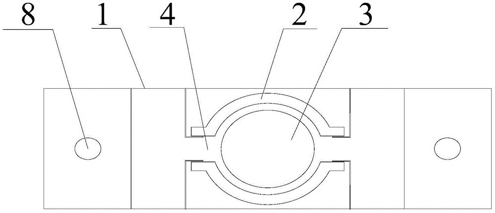
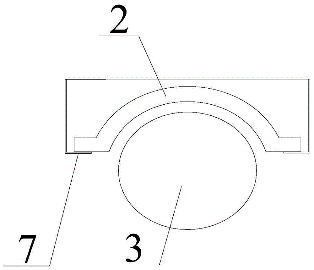
[0037] figure 1 A top view of a ball clamping device provided by an embodiment of the present invention; figure 2 A front view of the magnet 2 and the metal ball 3 of a ball clamping device provided by an embodiment of the present invention; image 3 for figure 1 The front view of a ball-clamping sliding door and window shown; Figure 1-3 As shown, a ball clamping sliding device provided in this embodiment includes a bracket 1, and the bracket 1 includes a set of oppositely arranged side walls, and a main body of the sliding device is arranged between the two side walls;

[0038] The main body of the sliding device includes two oppositely arranged magnets 2, which are respectively connected to the side walls. The opposite surfaces of the two magnets 2 are provided with concave spherical surfaces, and the magnetic force of the magnetic poles on the opposite surfaces of the magnets 2 is the same, and the concave spherical surfaces half surround the metal. For the ball 3, the...

Embodiment 2

[0043] figure 1 A top view of a ball clamping device provided by an embodiment of the present invention; figure 2 A front view of the magnet 2 and the metal ball 3 of a ball clamping device provided by an embodiment of the present invention; image 3 for figure 1 The front view of a ball-clamping sliding door and window shown; Figure 1-3 As shown, a ball clamping sliding device provided in this embodiment includes a bracket 1, and the bracket 1 includes a set of opposite side walls, and a main body of the sliding device is arranged between the two side walls;

[0044] The main body of the sliding device includes two oppositely arranged magnets 2, which are respectively connected to the side walls. The opposite surfaces of the two magnets 2 are provided with concave spherical surfaces, and the magnetic force of the magnetic poles on the opposite surfaces of the magnets 2 is the same, and the concave spherical surfaces half surround the metal. For the ball 3, the center of ...

Embodiment 3

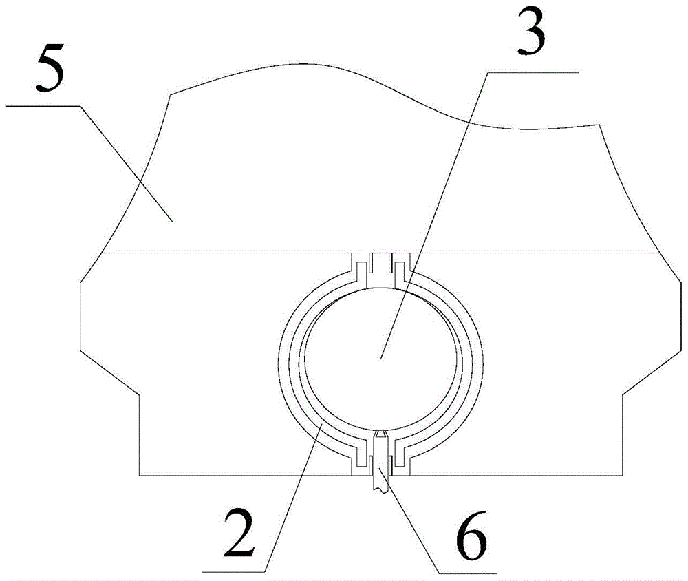
[0059] figure 1 A top view of a ball clamping device provided by an embodiment of the present invention; figure 2 A front view of the magnet 2 and the metal ball 3 of a ball clamping device provided by an embodiment of the present invention; image 3 for figure 1 The front view of a ball-clamping sliding door and window shown; Figure 1-3 As shown, the ball-clamping sliding door and window provided in this embodiment includes a door-window body 5 and a slide rail 6. The door-window body 5 is provided with a plurality of ball-clamping sliding devices, the track part is arranged in the annular gap 4, and the metal ball 3 is arranged on track.

[0060] The top and the bottom of the door and window body 5 are connected to the slide rail 6 through a plurality of ball-clamping sliding devices.

[0061] The top and the bottom of the door and window body 5 are respectively provided with two rows of ball-clamping sliding devices, which make the door and window body 5 run more smoo...


PUM


Abstract

The invention provides a ball clamping sliding device. The device comprises a bracket; the bracket comprises a pair of sidewalls, wherein the sidewalls are oppositely arranged; a sliding device body is arranged between the two sidewalls, comprising two oppositely-arranged magnets which are respectively connected with the sidewalls; inwards-concave spherical surfaces are arranged on the opposite surfaces of the two magnets; magnetic poles on the opposite surfaces of the magnets have the same magnetism; the inwards-concave spherical surfaces half encircle a metal ball; the centers of circles of the inwards-concave spherical surfaces are overlapped with the center of circle of the metal ball; an annular gap is formed between the two magnets and is respectively parallel to the two magnets. According to the ball clamping sliding device and a ball clamping sliding door window, the friction of the metal ball in rolling can be minimized during use, so that the frictional resistance can be reduced, and the style generated by opening and closing the door window can be reduced; the silence is ensured during use; the service life is prolonged; meanwhile, corresponding push supporting force can be generated during opening the door window, so that the force in opening and closing can be saved.

Description

technical field [0001] The invention relates to the technical field of door and window equipment, in particular to a ball clamping sliding device and a ball clamping sliding door and window. Background technique [0002] At present, a sliding door or a sliding window is a common way of setting doors and windows in buildings, which can be opened and closed in the horizontal direction without occupying additional space. Wherein, at present, commonly used push-pull mode is, a pulley is set on the moving door and window, a slide rail is set on the corresponding fixed door and window, and the opening or closing of the door and window is completed by the cooperation of the pulley and the slide rail. [0003] However, the way of using pulleys and slide rails is mechanical connection, and there will be a certain loss after long-term use. In severe cases, it may cause deformation of the pulleys or slide rails, thereby affecting the smoothness of opening and closing of doors and windo...

Claims


Application Information

Patent Timeline
Patent Type & Authority Patents(China)
IPC IPC(8): E05F1/00E06B3/46E05D13/00
Inventor 郭建东
Owner 郭建东
Why Eureka
Try Eureka