Flow path switching valve

A flow path switching and valve body technology, applied in multi-port valves, valve devices, engine components, etc., can solve problems such as stuck, insufficient piston concentricity, and achieve the effect of solving stuck

Inactive Publication Date: 2015-07-08
ZHEJIANG DUNAN MASCH CO LTD
View PDF8 Cites 6 Cited by
  • Summary
  • Abstract
  • Description
  • Claims
  • Application Information

AI Technical Summary

Problems solved by technology

[0005] The technical problem to be solved by the present invention is to provide a flow path switching valve, which can effectively solve the stuck problem caused by insufficient concentricity of the piston

Method used


Image

  • Flow path switching valve
  • Flow path switching valve
  • Flow path switching valve

Examples


specific Embodiment 1

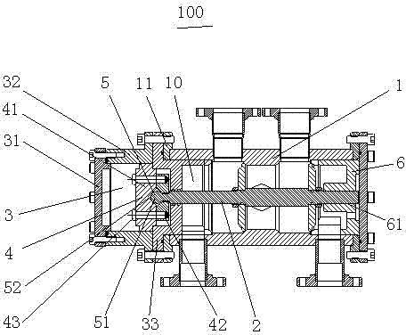
[0025] see figure 2 and image 3 As shown, a flow path switching valve 100 provided by the present invention includes: a valve body 1 having a valve chamber 10; a valve core 2 movably arranged in the valve chamber 10; a piston driving device 3 installed in the valve chamber 10; The first end of the valve body 1, the piston driving device 3 includes an end blind plate 31, which seals the end of the piston driving device 3; the piston drives the valve body 32, one end is fixedly connected to the end blind plate 31, and the other end is connected to the valve body. The body flange 11 is connected; the piston positioning seat 33 is fixedly installed between the piston-driven valve body 32 and the valve body flange 11, and limits the movement stroke of the piston 4; the piston 4 moves along the inner wall of the piston-driven valve body 32 and Connected with the valve core 2 through the ball joint 5; the bushing 6 is installed on the second end of the valve body 1 and has a guide...

specific Embodiment 2

[0030] see Figure 6 and Figure 7 As shown, the main structure of the flow path switching valve 200 in Embodiment 2 of the present invention is the same as that in Embodiment 1. For the understanding of the main structure, please refer to Embodiment 1, and the same parts also use the same reference numerals, which will not be repeated here.

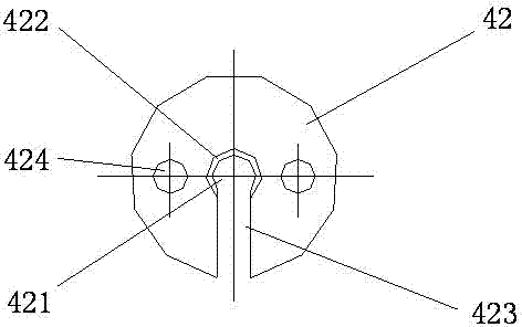
[0031] The main difference of this embodiment is that the ball head 51 is set separately from the valve core 2 . The advantage of this is that the piston pressing plate 42 may not be provided with a mounting groove communicating with the central through hole and extending radially to form a lateral opening, only the central through hole 421 needs to be provided, and the piston pressing plate 42 is set into the connecting ball of the valve core 2 After the parts of the head 51 (with the second diameter), they are constrained together by axial bolts (not shown) to complete the assembly. The piston-driven valve body 32 and the positioning...


PUM


Abstract

The invention discloses a flow path switching valve. The flow path switching valve comprises a valve body, a valve core movably arranged in a valve cavity, a piston driving device mounted at one end of the valve body and comprising a piston driving valve body, and a piston movably moving along the inner wall of the piston driving valve body and connected with the valve core through a bulb hinge, wherein the bulb hinge comprises a bulb and an accommodating groove; the bulb is arranged at the end part of the valve core; the accommodating groove is formed in the piston; the bulb and the accommodating groove are in contact in axial reciprocating motion; and the contact place is a spherical surface of the bulb and a plane or a spherical surface or a conical surface of the accommodating groove. Compared with the prior art, the flow path switching valve has the following advantages: the piston is connected with the valve core through the bulb hinge and the bulb and the piston are in movable contact in the reciprocating motion, so that the piston can rotate around the bulb hinge or can be inclined to a certain angle in the axial motion of the valve core and the piston has an excellent moving space.

Description

technical field [0001] The invention relates to the field of air conditioners, in particular to a flow switching valve for changing the flow direction of an air conditioner refrigerant. Background technique [0002] see figure 1 The flow switching valve 100' shown includes: a valve body 1', including a valve cavity; a valve core 2', movably arranged in the valve cavity; a piston driving device 3', installed at the first end of the valve body, And connected to the first end of the valve core; the flow path switching valve also includes: a bushing 6', installed at the second end of the valve body, and at least a part is located in the valve cavity, the bushing includes a guide hole, and the valve core The other end is movably arranged in the guide hole. And because one end of the piston driving device is directly inserted into the valve chamber and directly cooperates with the flow hole in the middle of the valve body, the centering of the valve core can be improved. [000...

Claims


Application Information

Patent Timeline
Patent Type & Authority Applications(China)
IPC IPC(8): F16K11/065
CPCF16K11/065
Inventor 王定军李维槽
Owner ZHEJIANG DUNAN MASCH CO LTD
Why Eureka
Try Eureka