Induction type wireless power supply system double-closed-loop constant output current control method

A wireless power supply, constant output technology, applied in the direction of electromagnetic wave systems, electrical components, circuit devices, etc., can solve problems affecting the quality of system power transmission, adjustment time growth, input voltage fluctuations, etc., to improve the quality of wireless power transmission, reduce Reactive power loss, the effect of reducing input voltage fluctuations

Active Publication Date: 2015-07-08
SOUTHWEST JIAOTONG UNIV +1
View PDF4 Cites 5 Cited by
  • Summary
  • Abstract
  • Description
  • Claims
  • Application Information

AI Technical Summary

Problems solved by technology

[0004] However, due to the problem of parameter selection, there is often a certain deviation between the expected output voltage of the Buck DC converter (the product of the input voltage and the duty cycle of the switching signal) and the actual output voltage, resulting in an increase in the overshoot of the constant current control process and The increase in adjustment time may also introduce serious input voltage fluctuations to the inductive wireless power transfer system, affecting the power transmission quality of the entire system

Method used


Image

  • Induction type wireless power supply system double-closed-loop constant output current control method
  • Induction type wireless power supply system double-closed-loop constant output current control method
  • Induction type wireless power supply system double-closed-loop constant output current control method

Examples


Embodiment

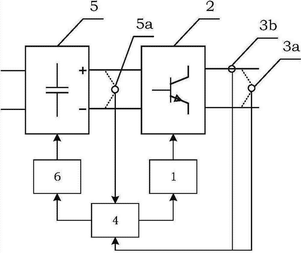
[0027] figure 1 It is shown that a specific implementation of the present invention is a double closed-loop constant current control method for a voltage-type inductive wireless power supply system, the steps of which are:

[0028] A. Outer loop control:

[0029] A1. The outer loop controller 1 generates a switching signal according to the current switching frequency to control the output voltage frequency of the high frequency inverter 2;

[0030] A2, the output voltage sensor 3a and the output current sensor 3b will detect the output voltage signal and output current signal of the high-frequency inverter 2, and after the signal processing unit 4 performs signal amplification, filtering, and analog-to-digital conversion, a high-frequency inverter is obtained The output voltage digital signal and output current digital signal of the device 2 are sent to the outer loop controller 1;

[0031] A3. The outer loop controller 1 applies short-time Fourier transform to the output vo...


PUM


Abstract

Provided is an induction type wireless power supply system double-closed-loop constant output current control method. The method comprises outer-loop controlling and inner-loop controlling. The outer-loop controlling comprises the steps that based on a short time fourier transformation method, real-time processing is carried out on output voltage and output current signals of a primary side high-frequency inverter, an equivalent impedance of a resonance circuit is calculated, it is judged whether an impedance phase-angle is in a threshold value range or not, if the impedance phase-angle exceeds a threshold value, an automatic frequency adjusting module is started, calculation is repeated, and the equivalent impedance of the primary side resonance circuit is judged until a system works in a resonance state. The inner-loop control comprises the steps that an input voltage theoretical value of the high-frequency inverter is calculated and corrected, and is used as an input voltage reference value of the inner-loop controlling. According to deviation of the input voltage reference value and a measuring value (actual input voltage of the high-frequency inverter), real-time calculation is carried out, a duty ratio of a switch signal of the deviation is removed, and a corresponding switch pulse signal is output. According to double-closed-loop constant output current controlling, energy output of an induction type wireless power supply system can be effectively controlled, and the wireless electric energy transmission quality is improved.

Description

technical field [0001] The invention relates to a double closed-loop constant output current control method for an inductive wireless power supply system. Background technique [0002] Inductive wireless power transfer technology is a technology based on the principle of electromagnetic field near-field induction, which comprehensively utilizes power electronic conversion technology, magnetic field coupling technology and control theory, and realizes that electrical equipment obtains energy from the power grid in a non-wire contact manner. The basic principle is to use a resonant converter to convert power frequency alternating current or direct current into high frequency alternating current, inject it into an energy emitting mechanism (such as a coil), and combine it with the principle of electromagnetic induction to excite a high frequency alternating magnetic field with the same frequency in space, so that The high-frequency electromotive force is induced in the pick-up ...

Claims


Application Information

Patent Timeline
Patent Type & Authority Applications(China)
IPC IPC(8): H02J17/00H02J50/12
CPCH02J5/005
Inventor 何正友李砚玲黄立敏麦瑞坤高仕斌李强
Owner SOUTHWEST JIAOTONG UNIV
Why Eureka
Try Eureka