Novel microphone structure

A microphone, a new type of technology, applied in the field of microphones, can solve the problems of affecting product life, product performance degradation, increasing production costs, etc., and achieve the effect of prolonging the service life

Inactive Publication Date: 2015-07-08
ZILLTEK TECH SHANGHAI +1
View PDF8 Cites 5 Cited by
  • Summary
  • Abstract
  • Description
  • Claims
  • Application Information

AI Technical Summary

Problems solved by technology

[0002] With the development of mobile multimedia technology, people's requirements for voice quality are getting higher and higher. In the design of sound transmission, MEMS (Micro Electro Mechanical System Microphone, microelectromechanical system microphone) microphone technology has the advantages of Thin and small size, high reliability, high temperature resistance and other excellent features make it widely used. In order to prevent external dust, liquid and other objects from entering the MEMS microphone and affecting the performance of the MEMS microphone, the MEMS microphone needs to be produced and assembled in a clean room However, in actual use, MEMS microphones will inevitably be affected by dust and other particles in the external environment, which will lead to product performance degradation and affect the service life of the product
[0003] In the prior art, a layer of dust-proof net is pasted on the outer surface of the acoustic through hole of the microphone to prevent particles such as external dust from entering the interior of the microphone. However, the volume of the microphone monomer is changed and more space is occupied. The space is not suitable for applications with strict installation size requirements. At the same time, it is necessary to change the sound guide rubber sleeve on the outside of the microphone unit, which increases the production cost.

Method used


Image

  • Novel microphone structure
  • Novel microphone structure
  • Novel microphone structure

Examples


Embodiment Construction

[0027] The following will clearly and completely describe the technical solutions in the embodiments of the present invention with reference to the accompanying drawings in the embodiments of the present invention. Obviously, the described embodiments are only some, not all, embodiments of the present invention. Based on the embodiments of the present invention, all other embodiments obtained by persons of ordinary skill in the art without creative efforts fall within the protection scope of the present invention.

[0028] It should be noted that, in the case of no conflict, the embodiments of the present invention and the features in the embodiments can be combined with each other.

[0029] The present invention will be further described below in conjunction with the accompanying drawings and specific embodiments, but not as a limitation of the present invention.

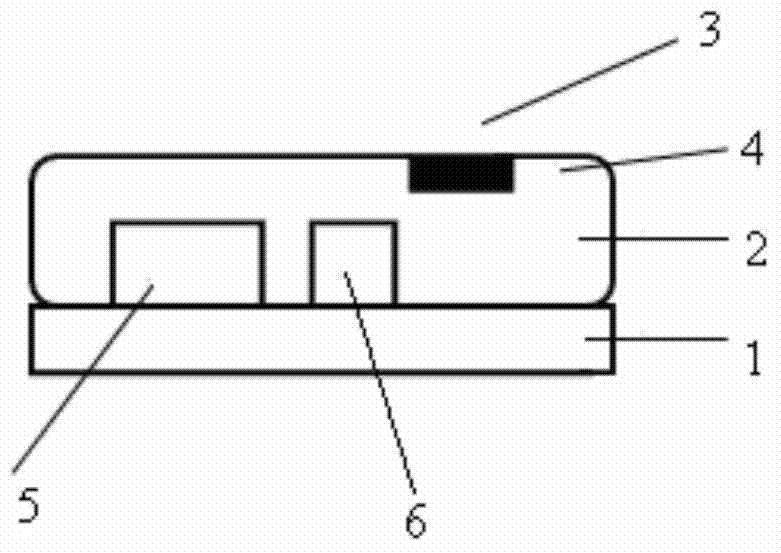
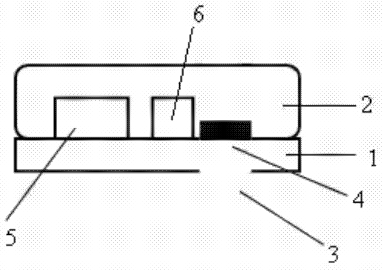
[0030] refer to figure 1 , figure 2 , a novel microphone structure, wherein, comprising a first layer structu...


PUM


Abstract

The invention relates to the technical field of voice processing equipment, more specifically, to a microphone. A new-type microphone structure comprises a first layer structure, a second layer structure located on the first layer structure, a microphone acoustic cavity formed by the first layer structure and the second layer structure, at least one acoustic hole for acquiring sound signals, which is arranged on the microphone acoustic cavity, and a dustproof component which covers the inside of the acoustic hole. The invention can prevent most of the dust particles and the moisture and the siphoning effect in actual use, which does not need to change the size of the existing microphone. It can be used in thin structures, and can prolong the service life of the microphone.

Description

technical field [0001] The invention relates to the technical field of voice processing equipment, in particular to a microphone. Background technique [0002] With the development of mobile multimedia technology, people's requirements for voice quality are getting higher and higher. In the design of sound transmission, MEMS (Micro Electro Mechanical System Microphone, microelectromechanical system microphone) microphone technology has the advantages of Thin and small size, high reliability, high temperature resistance and other excellent features make it widely used. In order to prevent external dust, liquid and other objects from entering the MEMS microphone and affecting the performance of the MEMS microphone, the MEMS microphone needs to be produced and assembled in a clean room However, during actual use, MEMS microphones will inevitably be affected by particles such as dust in the external environment, which will lead to product performance degradation and affect the s...

Claims


Application Information

Patent Timeline
Patent Type & Authority Applications(China)
IPC IPC(8): H04R19/04
CPCH04R17/00H04R1/086H04R19/005H04R19/04
Inventor 叶菁华
Owner ZILLTEK TECH SHANGHAI
Why Eureka
Try Eureka